

close
Choose Your Site
Global
Social Media

Author: Site Editor Publish Time: 2026-07-05 Origin: Site
For product engineers and procurement managers, designing adjustable furniture requires balancing user ergonomics and mechanical stability. You need components delivering fluid motion while maintaining rock-solid holds under heavy daily stress. Standard gas struts merely assist lifting. Precise positioning demands specialized locking capabilities. We see standard options failing where exact placement matters most. This guide evaluates why the Controllable Gas Spring is the standard for manual, power-free adjustability in modern design. By understanding the core mechanics, you can eliminate structural drift entirely. You will learn how to spec, evaluate, and integrate these essential units effectively. We explore critical engineering considerations to help you avoid common pitfalls. You will master the integration process for flawless manual actuation. This ensures your equipment performs perfectly under demanding real-world conditions.
Absolute vs. Elastic Positioning: Controllable gas springs allow infinite adjustment within a stroke length, offering either rigid locking (for load-bearing stability) or elastic locking (for shock absorption).
Power-Free Reliability: They replace complex electrical actuators in applications requiring manual, immediate adjustment (e.g., hospital beds, ergonomic desks).
Compliance & Safety: High-quality units meet BIFMA (furniture) or strict medical equipment standards, mitigating risks of sudden compression or leakage.
Adjustable equipment must hold static positions under variable loads. They cannot drift downward over time. Medical beds, ergonomic seating, and industrial workstations demand precise control constantly. Users expect an immediate response when they push a release lever. They also expect absolute immobility once they release the lever. Standard alternatives often fall short here. Friction hinges wear out rapidly over time. They lose holding power after repeated adjustment cycles. Standard gas struts push continuously to full extension. They cannot hold a mid-stroke position securely. Electric actuators require constant power sources. They introduce complex electronic failure points. You face frustrating design limitations when relying on these older methods.
Controllable pneumatic systems solve these hurdles directly. Engineers integrate an internal valve operated by a release pin. This allows the user to stop the stroke at any exact millimeter. The piston locks securely in place instantly upon release. They provide the perfect balance between fluid movement and rigid stability. We see this mechanical advantage transforming product usability daily. Users gain immense confidence knowing the equipment will not collapse. You eliminate the need for external power sources entirely. The entire mechanism remains self-contained and highly reliable.
Product engineers must consider the load dynamics during the design phase. Heavy equipment generates significant momentum during adjustment. A suddenly released locking mechanism must absorb this kinetic energy safely. Inferior mechanical locks often shear under sudden impacts. High-quality pneumatic locks cushion the initial shock internally. They distribute the force across the entire cylinder wall. This protects the internal seals from rupturing under pressure. You extend the operational lifespan of the entire furniture assembly securely.
Engineers must choose the correct locking mechanism based on the end-user application. You cannot apply a one-size-fits-all approach here. We frame this decision around how the furniture will operate daily. Will it support a human body or heavy medical machinery? Each scenario demands a completely different internal fluid dynamic.
Elastic locking mechanisms provide a cushioned feel upon locking. The internal valve separates pressurized nitrogen gas from more gas. Gas compresses slightly when subjected to heavy sudden loads. It offers a slight springing action even when fully locked. This slight give increases user comfort significantly. Ergonomic seating relies heavily on elastic locking systems. Backrests and passenger seats benefit greatly from the shock absorption. You ensure a smoother ride for the user during sudden movements. We highly recommend this type for any seating application.
Rigid locking in extension handles pulling forces aggressively. The valve separates incompressible hydraulic oil from the nitrogen gas. The oil chamber sits between the piston and the rod guide. Oil does not compress under pulling tension. This prevents the rod from pulling out or bouncing when pulled upward. Overbed tables and mobile equipment carts use this mechanism extensively. You prevent unwanted vertical movement during transit over bumpy floors. The table remains rigidly fixed even if someone lifts it forcefully.
Rigid locking in compression handles heavy pushing forces securely. The oil chamber sits between the piston and the base of the cylinder. It provides absolute immobility when heavy weight applies downward pressure. Medical beds use this rigid push system exclusively. Massage tables and heavy-duty adjustable desks also require absolute stability. A physical therapist pushing down heavily will not compress the table. You guarantee immobility under extreme downward loads.
| Mechanism Type | Internal Chamber Separation | Primary Physical Characteristic | Best Application Scenarios |
|---|---|---|---|
| Elastic Locking (Cushioned) | Gas separated from Gas | Slight compression under heavy load | Ergonomic seating, backrests, transit passenger seats |
| Rigid Locking in Extension (Rigid Pull) | Oil separated from Gas (above piston) | Prevents bouncing when pulled upward forcefully | Overbed tables, mobile medical carts, monitor arms |
| Rigid Locking in Compression (Rigid Push) | Oil separated from Gas (below piston) | Absolute immobility under heavy downward load | Medical beds, massage tables, industrial adjustable desks |
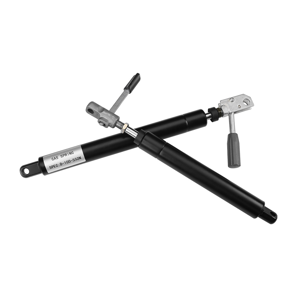
Evaluating a furniture gas spring requires analyzing specific technical dimensions carefully. You must calculate the exact load capacity and force in Newtons. We determine F1 force requirements based on the system's center of gravity. Pivot points dictate how much mechanical assistance the unit must provide. Over-speccing creates a harsh, jarring user experience during adjustment. Under-speccing causes equipment to drift downward under normal loads. Accurate kinematics modeling ensures flawless operation every time.
Cycle life and durability define product longevity fundamentally. Industry standards demand significant minimum performance thresholds. You should expect 50,000 to 100,000 cycles for premium components. Advise buyers to request detailed manufacturer testing methodologies. Do not rely solely on top-line cycle claims found on spec sheets. Real-world testing provides true reliability metrics. You want proof of testing under maximum load conditions consistently.
Release system compatibility impacts the user interface directly. You must evaluate the actuation method carefully during prototyping. Bowden cables work well for remote triggering across large furniture pieces. Push-buttons offer direct, simple actuation for localized adjustments. Hydraulic releases provide smooth, fluid control for high-end applications. The release lever ratio must match the internal valve resistance perfectly. This ensures smooth operation without excessive hand strain.
Safety and compliance govern modern manufacturing strictly. You must assess adherence to rigorous international standards. ISO 9001 certification guarantees consistent factory quality control. RoHS compliance ensures hazardous materials remain absent from the final product. Sector-specific standards dictate precise safety performance thresholds. BIFMA guidelines govern office furniture safety testing strictly. EN 60601 standards regulate medical equipment load factors heavily.
Calculate exact F1 force requirements based on maximum intended load.
Verify rigorous testing methodologies for manufacturer cycle life claims.
Match the release lever mechanical ratio to the furniture design.
Confirm strict adherence to ISO 9001 and sector-specific safety standards.
Integrating these components involves strict physical constraints and inherent risks. Installation angles dictate long-term performance directly. You must install the unit orienting the piston rod downward. Gravity pulls the internal oil down against the main seal. This keeps the internal rubber seal continuously lubricated. Dry seals crack quickly and cause premature nitrogen gas leakage. Proper orientation extends the functional lifespan of the unit significantly.
Temperature sensitivity affects force output consistently. Gas expansion and contraction represent inescapable physical realities. Force output changes by roughly 3.4% per every 10°C temperature change. High environmental heat increases the extension force noticeably. Extreme cold environments reduce lifting capacity significantly. Specify operating environments clearly during the initial design phase. You mitigate performance drops by planning for these exact temperature extremes.
Side-loading risks threaten structural integrity constantly. Warning against lateral forces remains vital for structural designers. These cylinders are engineered for axial loads exclusively. Pushing the rod sideways damages the internal microscopic seals instantly. Integration must include proper ball joints or sturdy clevis mounts. These articulated fittings absorb lateral stress safely. They allow the mechanism to move naturally without bending the steel rod.
Maintenance assumptions require clear communication to end-users. We acknowledge these units operate as permanently sealed, pressurized cylinders. They remain entirely maintenance-free throughout their operational life. You cannot repair or refill them in the field safely. A loss of pressure means internal damage has already occurred. If they fail, you must replace the entire unit immediately. Upfront quality control becomes your most critical defense strategy. Choose highly reliable components from the very beginning.
Evaluating manufacturing suppliers requires moving beyond basic catalog specifications. Customization capabilities separate excellent engineering partners from average vendors. Look for suppliers offering specific performance modifications. They should adjust internal progression rates to match your ergonomic goals. Terminal damping modifications prevent harsh impacts at full extension. They must customize release pin travel distances precisely. Avoid vendors merely selling rigid, off-the-shelf sizes.
Prototyping and lead times dictate your project launch schedule heavily. Assess the supplier's ability to provide low-volume custom test samples. You need physical mock-ups before committing to bulk manufacturing runs. Fast prototyping keeps development cycles on track and under budget. Delays in receiving samples cascade into missed product launch dates quickly. Choose partners prioritizing rapid engineering support.
Warranty terms and defect rates reveal true manufacturing quality openly. Request verifiable data on acceptable historical defect rates. Ask for explicit details regarding their warranty claim processes. Transparent vendors share this internal information willingly. They stand firmly behind their engineering and assembly protocols. High defect rates indicate poor internal cleanliness during cylinder assembly.
Next-step action involves initiating direct technical consultation immediately. We recommend starting discussions holding a complete engineering schematic. Allow the supplier's engineering team to calculate precise mounting points. Let them determine the exact nitrogen gas pressure required. Collaborative engineering prevents costly redesigns and safety failures later. Trusting expert guidance ensures your mechanical integration succeeds flawlessly.
Controllable gas springs define the ultimate user experience of adjustable equipment. They provide the critical balance between smooth motion and secure locking. We rely on them to ensure the safety of heavy-duty furniture designs. Careful selection of the locking type prevents dangerous unwanted movement. You must choose between rigid and elastic mechanisms based on specific applications. Rigorous supplier vetting remains the key to avoiding costly post-launch warranty issues. Evaluate customization capabilities carefully and request comprehensive prototyping early. Consult an experienced mechanical engineer to finalize your complex kinematics modeling. Request a custom force calculation for your specific prototype today. Implement these strict guidelines to achieve flawless mechanical performance across your product line.
A: Standard springs push continuously to full extension without stopping. Controllable springs feature a built-in internal valve and external release pin. This mechanism allows the user to lock the stroke securely at any point along its entire path.
A: Force is calculated based on the precise weight of the moving part. You must measure the exact distance to the pivot point and the mounting coordinates. Always consult the manufacturer's engineering team for exact kinematics modeling to ensure safety.
A: No. Due to extremely high internal pressures, they operate as permanently sealed units. A loss of pressure indicates irreversible seal wear or rod damage. The entire unit must be replaced immediately to ensure continued user safety.
A: Yes. Excessive cable length or sharp routing bends increase internal friction significantly. This requires much more hand force to trigger the valve open. It can also cause the pin to stick open, leading to unwanted equipment movement. Routing paths must remain direct.


