

close
Choose Your Site
Global
Social Media

Author: Site Editor Publish Time: 2026-07-03 Origin: Site
Achieving precise, variable motion control in industrial, medical, or heavy-duty applications often presents a significant engineering challenge. Standard pneumatic struts simply fail when applications require dynamic holding, dampening, and multi-position locking. This is where a Controllable Gas Spring becomes an essential component rather than a generic commodity. We can easily distinguish these advanced units from basic gas struts by their internal valve systems. They allow you to securely halt the stroke at any exact position.
Our objective is to move beyond basic definitions. We want to provide a rigorous technical evaluation framework. Engineers and procurement teams can use it to specify the correct gas springs for upcoming manufacturing runs. You will learn the mechanics behind these devices. You will evaluate rigid versus elastic variants and identify critical implementation risks before finalizing your designs.
A controllable gas spring utilizes an internal valve mechanism to allow engineers and end-users to halt or adjust the stroke at any point.
Often referred to interchangeably with a *lockable gas spring*, controllable variants offer distinct differences in elastic vs. rigid locking capabilities.
Selecting the right component requires evaluating load capacity, cycle-life expectations, and environmental compliance, rather than just unit cost.
Implementation risks primarily stem from incorrect stroke calculation and side-loading wear, which drastically reduce operational lifespan.
Understanding the internal dynamics helps you specify the correct unit for your project. A pressurized cylinder contains nitrogen gas and specialized hydraulic oil. The internal pressure differential across the piston drives the rod outward. We call this primary movement extension. The nitrogen gas acts as the core energy storage medium. It exerts a predictable, consistent force against the piston head area.
The valve mechanism sets controllable models apart from standard struts. A central release pin typically runs through the center of the piston rod. This pin acts as your mechanical interface. Here is exactly what happens during operation:
Actuation: You depress the trigger pin, opening the internal valve. Gas and oil flow freely through internal channels. They bypass the piston head entirely. This equalizes the pressure and lets you move the rod to your desired position.
Locking: You release the pin. The internal valve seals shut instantly. The fluid flow stops completely. The stroke locks firmly in place due to the isolated pressure zones.
Damping and speed control dictate the ultimate safety of heavy-load applications. The internal orifice size within the piston controls extension and compression speeds. A smaller orifice restricts fluid flow, slowing the movement. Oil volume manages end-damping. A specific volume of oil pools at the end of the cylinder. As the piston reaches full extension, it passes through this oil. This hydraulic cushion prevents jarring impacts. It protects hinges, structural mounts, and users from sudden stress spikes.
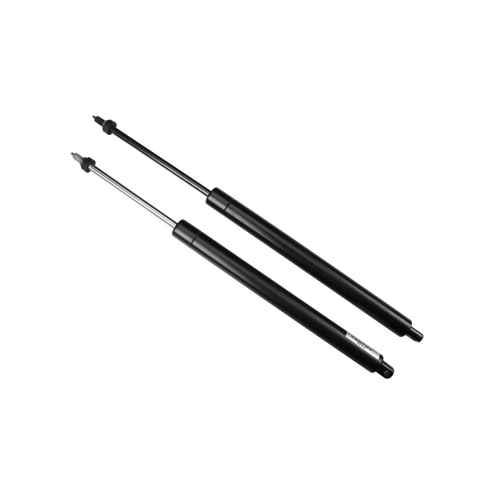
Engineers often confuse the terminology surrounding motion control hardware. We divide these solutions into three distinct categories based on their internal physics. Choosing the right category ensures mechanical safety and user comfort.
These are the most common units found in everyday products. They lack internal valves or trigger pins. The gas flows constantly through a small hole in the piston. Their primary use case involves simple open/close assist functions. You will find them lifting automotive tailgates or simple access panels. Their main limitation is a complete lack of mid-stroke control. You cannot lock them in a halfway position.
An elastic lockable gas spring provides mid-stroke positioning with a built-in cushioning effect. The locking mechanism relies on separating two gas chambers. Because nitrogen gas remains compressible, the locked position retains a slight springiness. If you apply a heavy external load, the rod compresses slightly before holding firm. They work best for shock absorption and flexible positioning. Medical beds, ergonomic seating, and adjustable desks rely heavily on elastic locking to enhance user comfort.
Rigid variants deliver absolute mechanical stability. The internal design completely separates the oil chamber from the gas chamber. Since hydraulic oil acts as an incompressible fluid, the locked rod refuses to yield under pressure. They ensure zero compression or extension when locked under heavy load. You must use rigid variants for safety-critical locking applications. Yield or creep remains entirely unacceptable in heavy machinery panels, aerospace seating, and heavy industrial automation.
Here is a quick reference chart for category comparison:
| Feature | Standard Gas Spring | Elastic Locking | Rigid Locking |
|---|---|---|---|
| Mid-Stroke Control | No | Yes | Yes |
| Locking Medium | N/A | Nitrogen Gas | Hydraulic Oil |
| Deflection Under Load | N/A | Moderate (Cushioned) | Zero (Solid Hold) |
| Primary Application | Tailgates, Hatches | Ergonomic Seating | Machinery Panels |
Selecting the optimal component requires deep technical analysis. You cannot simply guess the required force or ignore environmental factors. Engineering teams must evaluate four critical pillars before finalizing their specifications.
Manufacturers measure gas spring force at four distinct points: F1, F2, F3, and F4. F1 represents the nominal extension force. You must calculate the exact extension force (measured in Newtons) required to move your load. You need three critical variables to calculate this correctly. You must determine the weight of the moving flap. You must identify the flap's center of gravity. You must plot the exact mounting points for the hinges and the spring ends. Miscalculating the moment arm leads to either sluggish movement or aggressive, dangerous snap-back.
The progression ratio describes the relationship between the initial extension force (F1) and the final compression force (F3). As the rod enters the cylinder, it displaces internal volume, increasing the internal pressure. A higher progression ratio means the spring feels much stiffer at the end of its stroke. Evaluating this ratio ensures a consistent user experience. A lower ratio provides smoother, more predictable mechanical safety across the entire movement arc.
Industrial applications expose components to severe operating conditions. Standard seals function reliably between -20°C and +80°C. Extreme environments demand specialized Viton seals. You must also assess corrosion resistance. Look for components subjected to rigorous salt spray testing. Coastal or marine applications require 316L stainless steel rather than standard coated steel. If you design equipment for the food processing or medical industries, you must specify food-grade lubricants and FDA-compliant materials.
The internal valve requires an external actuation system. You must determine the required release force. High-pressure springs require more force to push the central release pin. You must integrate external hardware smoothly into your product design. Common integration options include:
Push-button mechanisms: Ideal for direct, localized control on handles.
Bowden cables: Essential for remote actuation when the spring sits deep inside a machine chassis.
Hydraulic release systems: Used in heavy-duty applications routing control to a central panel.
Lever releases: Simple, robust mechanical solutions for adjustable seating.
Even perfectly specified components fail if you install them incorrectly. Understanding common failure modes helps you design better structural mounts and extend the operational lifespan of your product.
Side-loading remains the absolute primary cause of premature failure. Gas springs handle axial loads exclusively. They push and pull in a straight line. Lateral forces push the piston rod against the internal seal. This unequal pressure degrades the seal rapidly, leading to instantaneous gas loss. You can mitigate this risk by using specific mounting hardware. Always use ball joints or clevis mounts instead of rigid eyelets. These articulated mounts absorb minor misalignments in your chassis, protecting the rod from lateral stress.
Standard lifecycle testing in laboratory conditions routinely achieves 50,000 to 100,000 cycles. Real-world variables drastically alter these numbers. Dust, abrasive debris, and metal shavings settle on the exposed rod. When the spring compresses, this debris scores the rod's surface. These micro-scratches tear the internal seals. Extreme temperature fluctuations also harden rubber seals prematurely. You should consider adding protective rubber bellows to the rod if you deploy equipment in harsh, dusty environments.
Engineers frequently ignore proper installation orientation. You must always design your assembly for rod-down installation. Keeping the rod pointing downward allows the internal hydraulic oil to pool over the main seal. This constant lubrication prevents the rubber seal from drying out and cracking. Rod-down orientation also ensures proper end-of-stroke damping. If you install it rod-up, the piston hits the gas pocket at the end of the stroke, causing a harsh, un-damped mechanical shock.
Moving from theoretical CAD models to physical assembly requires a rigorous prototyping phase. Skipping this step leads to massive production delays and sub-optimal product performance.
Relying purely on off-the-shelf specifications carries immense risk. Friction within your hinges, varying material densities, and slight manufacturing tolerances all alter the required force. You should always request adjustable-force prototypes. We call these ventable gas springs. They arrive fully pressurized. You install them onto your physical prototype. If the force feels too strong, you use a specialized tool to bleed out small bursts of gas. You repeat this until the kinematics feel perfect. You then measure the final force and order your production run based on that exact specification.
Not all manufacturers maintain the strict quality controls required for critical motion components. Look for manufacturing partners offering custom force calibration. They should fill springs to your exact Newton requirements rather than forcing you into pre-set intervals. Demand traceable ISO 9001 certifications. This guarantees repeatable quality across large volume runs. Finally, insist on transparent lead times for volume production. Prototypes might arrive in days, but you need certainty that bulk orders will meet your assembly line schedule.
Specifying a controllable gas spring requires rigorous mechanical analysis. It is an exercise in balancing complex load dynamics, locking rigidity, and long-term environmental durability. You cannot treat these components as afterthoughts. By understanding the differences between elastic and rigid locking, you protect end-users from sudden structural failures.
We advise engineering teams to fully finalize their CAD kinematics first. Establish your baseline load calculations and pinpoint your center of gravity before requesting a supplier consultation. Precise data eliminates guesswork and speeds up the prototyping phase.
Take the next step in your design process today. Download a technical spec sheet, utilize a digital force calculator, or contact an engineering team for custom prototype development.
A: Standard sealed units cannot be adjusted upwards. However, specialized ventable units allow gas to be released via a built-in valve to decrease force during the prototyping phase. Once dialed in, production units are filled to that exact specification.
A: Elastic locking uses gas on both sides of the piston, allowing a slight, cushioned bounce when locked. Rigid locking separates an oil chamber to prevent any movement when locked, crucial for high-load, static holds.
A: While rated for tens of thousands of cycles, actual lifespan depends strictly on avoiding side-loading, maintaining proper rod-down orientation, and protecting the rod from scoring or abrasive debris.


