

close
Choose Your Site
Global
Social Media

Author: Site Editor Publish Time: 2026-06-30 Origin: Site
In industrial design and ergonomic manufacturing, the difference between adequate motion and precision control often comes down to the component level. Engineers must constantly evaluate whether basic lift assistance suffices or if precise positioning remains critical for the end product. These early hardware choices directly dictate the final product's safety, usability, and mechanical lifespan.
While standard lifting components provide reliable lift assist and counterbalance, evolving safety regulations and user-experience demands increasingly require controllable variants. Choosing the wrong cylinder can introduce critical safety hazards or force engineering teams to add clumsy external locking mechanisms. If operators lose control of a heavy panel, structural damage and severe injuries often follow.
This guide provides an objective, specification-focused comparison between the two primary cylinder types. We will help engineering and procurement teams evaluate physical trade-offs, mitigate implementation risks, and align component selection tightly with specific application requirements. You will learn how to parse key mechanical differences and follow exact integration steps to streamline your next product design cycle.
Core Difference: Standard gas springs deliver a fixed, pre-calculated force profile for basic opening/closing; controllable gas springs feature internal valve mechanisms allowing for infinite positioning, variable speed, or rigid locking.
Cost vs. ROI: Controllable units require higher initial capital and more precise integration but eliminate the need for secondary mechanical locks or brakes.
Implementation Risk: The primary failure point when upgrading to controllable springs involves improper cable routing or misaligned release head actuation, requiring strict adherence to design tolerances.
Decision Driver: If the application requires mid-stroke holding, variable damping, or dynamic load accommodation (e.g., medical beds, ergonomic workstations), a controllable gas spring is necessary; for static, predictable loads (e.g., engine hoods, basic access panels), standard variants remain optimal.
To make informed design choices, you must first understand the baseline internal structure. A standard gas spring features a straightforward yet highly effective design. Manufacturers seal highly pressurized nitrogen gas and a small volume of lubricating oil inside a robust steel cylinder. The internal assembly relies on a simple piston containing a fixed bypass orifice. When the rod compresses or extends, gas flows freely through this permanent opening.
This constant volume displacement delivers a fixed, unalterable extension force based strictly on the initial charge pressure. Engineers calculate this pressure during manufacturing, and you cannot adjust it later in the field. The oil pool located near the end of the cylinder acts as a natural dampener. As the piston pushes through the oil at the end of its stroke, it slows down. This prevents jarring impacts and protects the main rod seal from sudden kinetic shock.
The upgrade to variable control introduces complex internal valving. A controllable variant integrates a highly specialized piston valve into the internal architecture. Actuation typically occurs via a mechanical release pin located precisely at the end of the exposed piston rod. When you depress this pin using an external lever or button, the internal valve opens. Nitrogen gas and oil can then flow freely between the divided internal chambers.
Releasing the pin instantly shuts the internal valve. This action interrupts the fluid transfer completely and locks the piston firmly in place. You can regulate the motion mid-stroke for exact positioning. Performance capabilities vary based on the specific fluid-to-gas ratio and the valve's geometric design. You might select rigid locking in tension, rigid locking in compression, or elastic locking. Elastic locking relies mostly on compressed gas, which provides a slight cushioning effect upon locking. Rigid locking utilizes dense oil chambers to prevent any post-lock compression, ensuring the rod remains entirely immobile under heavy loads.
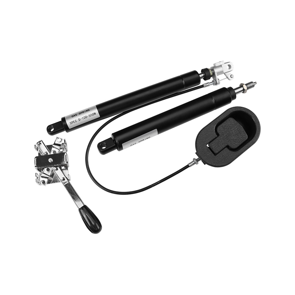
Standard components eventually hit their mechanical limits when introduced to dynamic human environments. You will notice these limits clearly when a basic component fails the success criteria for advanced kinematics. End-users often require custom positioning across various modern industries. Consider heavy-duty monitor arms, articulating hospital beds, or adjustable passenger seating. People need to stop the physical load at varying heights to match their unique ergonomic requirements.
A standard cylinder simply pushes the load to its maximum extension unless held back by constant, physical human force. It offers zero mid-stroke locking capability. Furthermore, standard end-of-stroke damping often fails to provide sufficient safety for severe load deceleration. Heavy machine guards, massive industrial access panels, or aerospace compartments can slam shut aggressively if the fixed damping cannot absorb the generated kinetic energy. This lack of control damages surrounding hinges and presents severe pinch hazards to operators.
In these challenging scenarios, engineers pivot to advanced control alternatives. A Controllable Gas Spring acts as a robust, single-component solution for complex motion problems. It addresses strict safety compliance directly by locking instantly upon the release of the actuation mechanism. If an operator accidentally lets go of a heavy steel panel, it stops moving immediately mid-air.
This fail-safe behavior prevents crush injuries and expensive equipment damage. Adopting this technology allows you to strip away complex, multi-part mechanical counterbalance systems. Instead of combining basic cylinders with secondary friction brakes, locking pins, and mechanical latches, you install one streamlined unit. You simplify the assembly bill of materials while simultaneously upgrading the smoothness and reliability of the end-user experience.
Specifying the correct cylinder requires mapping technical features directly to desired mechanical outcomes. Standard units provide a highly predictable cycle life and lower upfront manufacturing complexity. They remain ideal for high-volume, low-complexity assembly lines. Think of basic toolbox lids, automotive engine hoods, or simple storage compartments. Conversely, controllable units offer elastic or rigid locking capabilities. They suit high-end environments requiring user-defined ergonomics or strict load-holding compliance.
Scalability and sourcing also diverge significantly between the two technologies. Standard sizes remain universally stocked across global supply chains. You can quickly procure off-the-shelf dimensions for rapid prototyping and mass production. However, specific controllable actuation ratios often require custom engineering. You must calculate precise release pin travel, actuation force, and locking rigidity based on your frame design. This bespoke engineering extends lead times slightly but guarantees exact mechanical alignment for premium products.
Lifecycle durability and environmental compliance require careful evaluation during the design phase. Controllable springs contain more complex internal seals to manage the dynamic, high-pressure valve switching. You must assess cycle-life expectations rigorously when deploying them in harsh physical environments. Intrusive dust, abrasive debris, or extreme temperature fluctuations can degrade these intricate seals faster than standard ones. Certain industries dictate strict environmental standards. Medical and aerospace applications often require compliance upgrades, prompting manufacturers to use food-grade oils or apply specialized protective coatings for lockable variants.
| Evaluation Criteria | Standard Variant | Controllable Variant |
|---|---|---|
| Motion Control | Continuous extension to full stroke. | Infinite mid-stroke positioning and holding. |
| Internal Sealing | Simple main rod seal and piston. | Complex multi-chamber valve seals. |
| Locking Type | None (requires external physical latch). | Elastic, rigid in tension, or rigid in compression. |
| Environmental Sensitivity | Moderate tolerance to dust and debris. | High sensitivity; requires strict seal protection. |
Integrating controllable variants introduces unique mechanical challenges that engineers must anticipate early. You must account for actuation system complexities during the initial CAD modeling phase. You cannot simply bolt these cylinders into place without planning the release mechanism.
Space Claim Requirements: You must design dedicated physical space for routing Bowden cables, mounting release levers, or integrating hydraulic push-buttons. These components connect the human user interface down to the release pin.
Actuation Tolerances: The release pin requires highly precise travel distances, often measured in fractions of a millimeter. If you configure the mechanism incorrectly, the valve will not open fully, resulting in sluggish movement.
Creeping Cylinders: Continuous micro-actuation poses a major risk. If you overtension the routing cables, the pin remains slightly depressed at all times. The internal valve never fully seals, causing the cylinder to "creep" and lose its holding position over time.
Mounting and side-loading hazards apply universally to all pressurized cylinders. Both types remain highly susceptible to premature seal failure from lateral forces. When side loads push against the rod, they deform the lip seal, allowing pressurized nitrogen to escape. Controllable springs remain far more sensitive to this issue. The actuation pin mechanism relies on perfect linear alignment to function. If side loads bend the rod slightly, the internal valve may jam permanently.
To mitigate these integration risks, follow strict mounting protocols. Never hard-mount the cylinder rod tightly into a rigid frame without flexibility. Always utilize ball joints, self-aligning clevis brackets, or swivel eyes at the mounting points. Ensure the physical load path passes perfectly through the center axis of the cylinder. Finally, protect the exposed piston rod from weld spatter, paint, and abrasive dust during the factory assembly process.
Choosing the correct component requires a systematic approach. Do not guess based on visual similarity. Follow this practical decision matrix to shortlist the optimal cylinder for your specific assembly architecture.
Define the Motion Requirement: Ask yourself if the load needs to stop and hold securely at multiple points along the stroke. If the operator requires custom positioning, choose the controllable route immediately. If the load only requires simple assistance from fully closed to fully open, a standard model suffices.
Evaluate Budget vs. Assembly Time: Weigh the broader mechanical ecosystem. Calculate the assembly time required to install a standard unit alongside external locking hardware, brackets, and latches. Compare this against integrating a single controllable unit. The integrated unit often saves significant labor time and inventory tracking, offsetting a higher individual part value.
Determine Control Type: If you select a controllable cylinder, you must specify the exact locking behavior. Choose elastic locking for applications requiring slight shock absorption, like passenger seating or ergonomic office chairs. Select rigid locking for immobile stability, such as a surgeon's operating table or a heavy drafting desk.
Calculate Precise Ratios: Standardize your mounting pivot points. Calculate precise stroke-to-force ratios based on the exact center of gravity of your physical load. Account for the weight of the panel, the angle of opening, and the distance to the hinges.
Execute Fatigue Testing: Never skip physical validation. Request highly accurate CAD models to verify internal clearances. Order physical prototype samples and run fatigue testing under actual dynamic load conditions. This verifies seal integrity and ensures actuation smoothness before mass production begins.
Selecting between a controllable gas spring and a standard variant is not a matter of one being universally better. It demands a strict alignment of component capabilities with your actual mechanical realities. Understanding the precise kinematic needs of your end-user dictates the final choice. Do not over-engineer simple access panels or engine hoods where continuous, reliable extension completely satisfies the requirement.
Conversely, never compromise on safety or ergonomics for dynamic, user-operated loads. If the load requires mid-stroke holding or immediate fail-safe stopping, invest in the complex valving required to secure it properly.
Take immediate steps to validate your design assumptions today. Consult with dedicated application engineers early in your design cycle to verify complex load calculations and structural force vectors. Review standard and controllable CAD files thoroughly before finalizing your pivot points. Construct a physical mock-up to test cable routing and release pin actuation hands-on. This rigorous validation ensures your final assembly operates safely, smoothly, and reliably throughout its intended lifespan.
A: No. The internal piston and valve architecture are fundamentally different. A standard unit uses a simple fixed orifice for basic gas displacement. A controllable unit relies on a specialized, actuatable valve mechanism. Switching requires replacing the entire cylinder completely and adding an external actuation mechanism like a Bowden cable or push-button lever.
A: They are not inherently less reliable, but their complex internal valving requires stricter adherence to exact mounting tolerances. Improper cable tensioning remains the leading cause of perceived failure. If external cables are too tight, they cause continuous micro-actuation, leading to pressure leaks and unintended load movement.
A: While the end fittings, such as eyelets or ball studs, can be identical on the main cylinder body end, the rod end differs significantly. The rod end of a controllable spring requires highly specific hardware. It must house the release pin and the accompanying actuator head to function correctly within the wider assembly.
A: Both components rely heavily on internal gas pressure, which fluctuates naturally with ambient temperature changes. Standard practice expects a 3.4% force change per 10°C. However, extreme cold affects them differently. Cold temperatures can noticeably stiffen the oil bypass in controllable units, which slightly alters actuation response times and locking engagement speeds.


