

close
Choose Your Site
Global
Social Media

Author: Site Editor Publish Time: 2026-10-12 Origin: Site
In modern industrial design, smooth and precise motion control is non-negotiable. Sudden equipment drops do more than disrupt your workflow; they actively threaten workplace safety. Whether you are engineering a heavy-duty access panel on CNC machinery or developing an ergonomic medical operating table, you must ensure that all moving parts adjust seamlessly and secure reliably.
Pick the wrong motion control component, and you risk severe mechanical failure. Standard struts or basic dampers frequently fall short when your design requires infinite adjustability and unyielding locking capabilities. Unstable positioning or unexpected mechanical drift are not merely inconveniences. In harsh industrial environments, they represent significant safety hazards and inevitably lead to costly equipment downtime.
The optimal solution for these complex positioning challenges is the controllable gas spring. Unlike standard variants, this advanced mechanism allows operators to stop and lock a heavy component at any exact point along its entire stroke length. This comprehensive guide walks you through the essential technical specifications, locking mechanism types, precise load calculations, and environmental variables needed to specify the perfect adjustable component for your next heavy-duty project.
Controllable gas springs feature an internal valve mechanism allowing users to stop and lock a moving part at any exact point along its stroke.
The choice between elastic locking and hydraulic locking depends entirely on whether the application requires shock-absorbing cushioning or absolute structural rigidity.
Accurate mathematical calculation of force, stroke length, and mounting geometry is non-negotiable for achieving optimal mechanical performance and safety.
Environmental variables, including temperature extremes and abrasive chemical exposure, dictate the specific materials and sealing technologies required.
Partnering with an experienced manufacturer ensures the delivery of a precision component rigorously tested for your specific load requirements.
To make an informed specification, engineering teams must first understand the internal mechanics at play. A standard gas strut consists of a piston rod, a sealed cylinder, pressurized nitrogen gas, and a small amount of lubricating oil. It provides a continuous, constant force to assist in lifting or lowering a load from point A to point B. However, it cannot be stopped mid-stroke.
A controllable alternative operates on a significantly more advanced principle. It incorporates a specialized internal valve mechanism built directly into the piston, separating the cylinder into two distinct pressure chambers. This system is operated via a release pin located at the end of the piston rod.
When an external actuator depresses this release pin, the internal valve opens. This action allows the nitrogen gas or oil to flow freely between the two chambers, enabling the rod to extend or compress smoothly. The moment the operator releases the actuator, the internal valve snaps shut instantly. The fluid or gas is trapped, blocking further movement and locking the piston rod firmly in its current position. Consequently, this capability transfers the control of massive loads directly to the user, allowing for micro-adjustments without any mechanical drift.
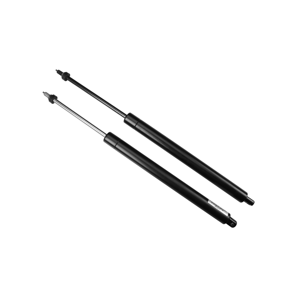
Selecting the correct locking behavior is arguably the most critical decision in the engineering procurement process. The internal medium determines exactly how the spring behaves when locked under a heavy physical load. Not all locking mechanisms yield the same physical results.
In an elastic locking configuration, compressible nitrogen gas is present in both chambers on either side of the piston valve. Because gas is inherently compressible, the locked spring will exhibit a slight bounce or yield when a sudden, heavy load is applied to it.
This cushioning effect is highly desirable in specific ergonomic applications. For instance, in passenger vehicle seats or lightweight adjustable monitors, a slight elastic deflection absorbs sudden shocks. This significantly improves user comfort while preventing mechanical stress fractures on the surrounding structural frame.
For applications demanding absolute stability with zero yield, engineers must specify a hydraulic locking gas spring. In these robust models, the locking chamber is filled with oil rather than gas. Since liquids are virtually incompressible, the piston rod remains completely rigid when the valve is closed. This yields zero bounce even under extreme forces.
Specifically, hydraulic locking is further divided into two configurations based on the orientation of the oil chamber:
Rigid in Compression: The oil blocks the piston from moving inward. This is critical for heavy-duty industrial workbenches or hospital beds, where the strut must support a massive downward load without collapsing.
Rigid in Tension: The oil blocks the piston from pulling outward. This setup is utilized where the locked mechanism must resist being pulled apart by hanging weights or tension forces.
| Locking Type | Internal Medium | Behavior Under Load | Ideal Industrial Applications |
|---|---|---|---|
| Elastic Locking | Nitrogen Gas | Slight cushioning and bounce | Ergonomic seating, monitor arms, lightweight access panels |
| Rigid in Compression | Oil | Zero yield when pushed inward | Medical operating tables, heavy industrial workbenches |
| Rigid in Tension | Oil | Zero yield when pulled outward | Tensioned hanging displays, specialized steering columns |
Before requesting a technical drawing from a manufacturer, defining several core specifications is mandatory. Missing these parameters easily leads to premature seal failure, structural instability, or an inability to support your target load.
The lifting force of a gas cylinder is measured in Newtons. Calculating the exact force required ensures the component can lift the load smoothly without requiring excessive manual effort from the operator. If your application involves variable weights or prototype testing, engineers often specify an adjustable gas spring equipped with a specialized bleed valve. Standard industrial models typically offer force ranges from 50N up to 1200N. The bleed valve allows the installer to order a unit with maximum pressure and safely vent small amounts of nitrogen gas during installation to achieve the perfect ergonomic balance.
Two physical dimensions dictate the geometric fit within your mechanical assembly. The stroke length is the total linear distance the piston rod travels from a fully compressed state to a fully extended state. In contrast, the extended length is the total overall measurement from the center of the top mounting point to the center of the bottom mounting point when the unit is completely open. Common industrial stroke lengths range from 50mm for compact devices up to 500mm for large machine enclosures.
The progression ratio defines the force curve. As the piston rod pushes into the cylinder, it reduces the internal volume, causing the internal gas pressure to rise. Consequently, the mechanism exerts more force when fully compressed than when fully extended. A lower progression ratio means the force remains relatively flat and consistent throughout the stroke, which is highly preferred for smooth, user-friendly ergonomic adjustments.
A controllable unit is only as effective as its release mechanism. Depending on the spatial constraints and ergonomic design of the equipment, engineers can choose from direct push-buttons for compact spaces, lever handles for manual equipment, Bowden cable systems for remote actuation, or hydraulic foot pedals for hands-free medical applications.
Recent market analyses highlight a surging demand for automated and highly ergonomic workstations across the manufacturing and healthcare sectors. As workplace safety regulations become increasingly stringent globally, industries are rapidly moving away from traditional mechanical ratchets and friction hinges. Instead, there is a massive shift toward fluid, user-controlled motion systems that minimize musculoskeletal strain.
Furthermore, the push for miniaturization in aerospace and medical devices is forcing manufacturers to develop high-force locking springs housed within incredibly compact, lightweight cylinders. This demand drives rapid material science innovations in sealing technologies, ensuring that modern components can withstand higher internal pressures without expanding the outer tube diameter.
Understanding how different sectors deploy these advanced components helps procurement managers identify the specific requirements for their own unique use cases.
Medical environments demand absolute reliability, strict hygiene, and high load capacities. Hospital beds, overbed tables, surgical operating tables, and wheelchair tilt mechanisms rely heavily on rigid hydraulic configurations. Imagine a surgeon leaning their full body weight onto an operating table during a delicate procedure; the surface beneath them must not yield a single millimeter. Therefore, elastic locking is strictly prohibited here. Additionally, these units are often manufactured from medical-grade stainless steel to withstand harsh chemical sterilization protocols.
Industrial drafting tables, control room consoles, and assembly line workstations require frequent height and angle adjustments to accommodate different shift workers. In these settings, elastic locking springs provide the necessary height adjustment while offering a slight cushioning effect that protects both the heavy equipment and the user during sudden, rapid movements.
In harsh manufacturing facilities, operators frequently interact with heavy protective hoods, CNC machine access doors, and rugged industrial monitor arms. Integrating a precision position control spring allows a single maintenance worker to safely lift a 100-kilogram steel access panel with minimal effort. They can stop it securely at a 45-degree angle to perform internal repairs, trusting completely that the heavy hood will not drop unexpectedly.
Incorrect force calculations and improper mounting geometry are the leading causes of component failure. Rather than relying on estimation, engineers must utilize foundational mechanical formulas to ensure safety.
A simplified version of the standard calculation to determine required lifting force is: F = W x D / L x n + 15% Safety Margin.
F: Required spring force in Newtons.
W: Weight of the moving load in Newtons, which is mass in kilograms multiplied by 9.81.
D: Horizontal distance from the pivot point or hinge to the load center of gravity.
L: Vertical distance from the pivot point to the mounting point on the moving part.
n: Number of units used in the application, typically two for balanced load distribution.
The precise angle at which the cylinder is mounted significantly impacts both the required lifting force and the longevity of the internal seals. For optimal lubrication, gas springs should ideally be mounted with the piston rod pointing downward when in the resting or closed position. This specific orientation ensures that the internal lubricating oil rests directly on the main sealing package, keeping the rubber pliable and preventing the pressurized nitrogen gas from leaking over years of use.
Always consult with your supplier engineering team before finalizing your CAD models. Minor coordinate adjustments to the mounting brackets can drastically reduce the required force, thereby extending the cycle life of the strut and lowering overall manufacturing costs.
Industrial applications rarely exist in perfect, climate-controlled vacuums. The physical environment where the equipment operates dictates the material science behind your lockable gas spring selection, preventing premature degradation.
Gas pressure fluctuates naturally with temperature changes. A cylinder calibrated for room temperature will exert less force in freezing conditions and significantly more force in high-heat environments. Standard seals typically operate safely between -20°C and +80°C. For foundries, aerospace applications, or industrial freezers, engineers must specify specialized low-temperature or high-temperature synthetic Viton seals.
Standard industrial units are constructed from carbon steel with powder-coated cylinders and nitride-treated rods. However, applications exposed to marine environments, food processing plants, or harsh medical facilities will cause standard steel to rust rapidly. In these scenarios, specifying 304 or 316L stainless steel construction is mandatory to resist saltwater corrosion and harsh caustic cleaning chemicals.
In agricultural machinery, mining equipment, or heavy construction, abrasive dust is a constant threat. Dust settling on the piston rod can be dragged past the main seal during compression, scratching the internal chamber and causing rapid gas leaks. Specifying a unit with a heavy-duty wiper seal or an external protective metal tube is essential to maintain internal integrity in these rugged settings.
When procurement managers reach the final purchasing stage, they must decide between buying off-the-shelf standard units or partnering with a manufacturer for customized solutions.
Standard units are appropriate during the initial proof-of-concept phase or for simple, low-load applications where exact dimensions and force curves are not critical to user safety. They offer shorter lead times and lower upfront costs.
Conversely, industrial buyers must customize when dealing with heavy loads, strict ergonomic compliance, or extreme environments. Customization involves selecting specific end fittings, such as heavy-duty clevis forks or ball joints, fine-tuning the force settings to the exact Newton, and integrating specialized remote cable actuators tailored to the equipment chassis.
A reliable manufacturing partner should offer comprehensive engineering support, including 3D CAD modeling and load calculation verification. Ensure the supplier holds ISO 9001 certifications and can provide transparent documentation for rigorous quality control processes, such as 144-hour salt spray corrosion tests, tensile strength testing, and extensive dynamic fatigue cycle testing.
Choosing the right motion control mechanism ultimately depends on a deep understanding of the application weight, the required structural rigidity, and the surrounding environmental conditions. Precision positioning does more than just make equipment easier to use; it fundamentally elevates workplace safety and the perceived quality of the final industrial product.
Evaluate your specific load requirements carefully before making a procurement decision. By accurately calculating forces, selecting the appropriate hydraulic or elastic locking type, and protecting the unit from harsh environments, you ensure years of flawless operation. If you are developing a new industrial workstation or upgrading heavy machinery, visit Mirui Gas Spring to explore exact OEM replacements, request custom load calculations, and secure a tailored motion control solution designed specifically for your project.
Yes, but typically only in one direction. Certain adjustable models are manufactured with a built-in bleed valve. This allows operators to safely release small increments of nitrogen gas using an Allen key or specialized tool to lower the lifting force if the initial specification was too strong. However, once the gas is vented, force cannot be added back into the cylinder without returning the unit to the manufacturer for professional re-pressurization.
The primary difference lies in the internal architecture. A standard gas strut provides continuous pushing force to assist movement from closed to open but cannot be stopped mid-stroke. A lockable version features a sophisticated internal valve and an external release pin. When the pin is actuated, it allows movement; when released, it instantly blocks the flow of internal gas or oil, securely locking the piston rod at any exact position along its travel path.
In standard industrial conditions with proper vertical mounting, a high-quality hydraulic locking unit is designed to last between 40,000 and 100,000 actuations. The actual lifespan is heavily dependent on avoiding lateral side-loading forces, protecting the rod from abrasive debris, and operating strictly within the specified temperature ranges to prevent seal degradation.
It is highly discouraged to use generic replacements for heavy-duty applications. To ensure safety and mechanical functionality, you must match the exact physical and mechanical specifications of the original component. You must perfectly replicate the stroke length, extended length, force rating, locking type, and end fittings. It is always recommended to source exact OEM replacements or work with a specialized manufacturer to engineer a custom-matched part.
Releasing the mechanism requires actuating the pin located at the end of the piston rod. This is typically achieved using a compatible release head connected to a push-button, a lever, or a Bowden cable system. Once the pin is depressed by just a few millimeters, the internal valve opens, allowing the rod to move freely.
The most common cause of premature failure is side-loading. These components are designed to handle linear forces. When mounted at incorrect angles without proper pivoting end fittings like ball joints, lateral stress is applied to the piston rod. This uneven pressure quickly degrades the internal seals, leading to nitrogen gas leaks and a complete loss of locking force.


