

close
Choose Your Site
Global
Social Media

Author: Site Editor Publish Time: 2026-08-26 Origin: Site
Improperly sizing a gas spring in load-bearing applications introduces severe operational hazards. When hardware fails to support a heavy lid or an adjustable medical bed, the resulting sudden drops cause catastrophic equipment damage and operator injury. Standard gas struts provide continuous push or pull force, but they cannot safely lock loads in intermediate positions. This creates a complex engineering challenge. You must balance precise maneuverability with absolute holding rigidity.
Solving this problem requires a strict mathematical approach. Safe holding demands exact calculations of force, stroke length, center of gravity, and the internal locking mechanism type. Specifying the correct Locking Gas Spring ensures your application remains securely positioned under varying load conditions. This guide breaks down the mechanical framework required to specify, calculate, and implement the exact hardware for your load control requirements.
Sizing requires precise calculation of the application’s weight, physical dimensions, center of gravity, and mounting pivot points to determine the exact force (in Newtons) required.
Selecting between rigid (in compression or extension) and flexible locking mechanisms dictates the absolute safety and deflection limits of the application.
Environmental variables, particularly temperature fluctuations, directly impact internal pressure and must be factored into the safety margin of the specified lockable gas spring.
Proper mounting geometry is as critical as the spring specification itself to prevent side-loading and premature seal failure.
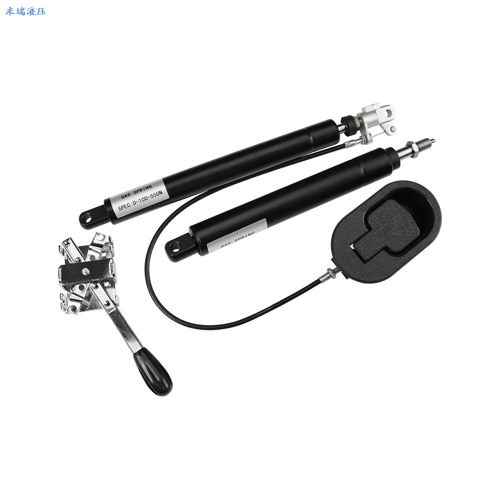
You need to know exactly what happens inside the cylinder before you specify a part. The internal fluid layout dictates how the unit handles static and dynamic loads on the shop floor. Guessing the internal mechanics leads to hardware that either bounces under pressure or seizes up entirely.
Standard struts use a basic piston with a bypass hole. Gas flows freely between the chambers. You get continuous extension force, but zero stopping power. A controllable gas spring fixes this by replacing the open bypass with a sealed internal valve system. The piston physically divides the cylinder into two isolated pressure zones. A release pin runs straight down the center of the hollow piston rod.
When an operator depresses that release pin—usually requiring only 1mm to 2.5mm of travel—the internal valve opens. The pressurized nitrogen gas and hydraulic oil rush between the two chambers. The rod extends or compresses based on the operator's physical input. The moment you release the pin, the valve snaps shut. Fluid flow stops instantly. The gas and oil are trapped in their respective chambers, locking the piston rod firmly in place. The integrity of this internal seal determines the maximum holding capacity before the rod begins to slip.
The physical location of the hydraulic oil inside the cylinder determines how the spring behaves when locked. You must select the correct type based on how much deflection your application can tolerate.
Flexible locking designs keep nitrogen gas on both sides of the piston valve. Gas is inherently compressible. When you lock the spring and apply a heavy external load, the rod will exhibit a slight bounce. It compresses slightly under weight and rebounds when the weight is removed. We use this dampening effect intentionally to absorb shock. It provides the necessary ergonomic give for seating mechanisms and workstation adjustments.
Rigid in compression designs place the entire hydraulic oil chamber directly in the path of the compression stroke. Oil is an incompressible fluid. Once the valve closes, the piston rod hits a solid wall of oil. It cannot be pushed inward. The mechanism firmly secures the rod, resisting movement even under massive downward loads. We specify this absolute rigidity to prevent heavy safety lids, machine guards, or medical beds from collapsing on operators.
Rigid in extension designs reverse this internal fluid layout. The oil chamber sits in the path of the extension stroke. When locked, the rod cannot be pulled outward. This secures the application against upward forces. We use this to prevent uncontrolled expansion or lifting in tension-loaded mechanisms.
Comparison of Gas Spring Locking Mechanisms
| Locking Type | Internal Fluid Arrangement | Deflection Behavior | Primary Application Use Case |
|---|---|---|---|
| Flexible | Gas on both sides of piston | Slight bounce under heavy load | Ergonomic seating, adjustable desks |
| Rigid in Compression | Oil blocks inward movement | Zero inward deflection | Heavy access panels, medical tables |
| Rigid in Extension | Oil blocks outward movement | Zero outward deflection | Tension-loaded mechanisms, safety restraints |
Accurate physical measurements dictate the success of your installation. You must map the exact physical properties of the moving component before calculating force. Relying on rough estimates guarantees a failed installation.
You must measure the exact weight and physical dimensions of the lid, panel, or surface. Do not rely on initial CAD mass properties alone. Manufacturing variances, added brackets, paint, and attached hardware change the final mass. Use a heavy-duty spring scale to measure the actual lifting power required on the physical prototype. Attach the scale to the exact point where the user will grab the panel. Pull perfectly perpendicular to the surface and record the peak weight.
Next, locate the Center of Gravity (CoG). For a uniform rectangular steel panel, the CoG sits exactly in the geometric center. However, attached handles, internal bracing, or uneven material distribution will shift the CoG significantly. You must map the CoG relative to the pivot hinge. As the panel moves through its opening arc, the horizontal distance between the CoG and the pivot point changes. This shift alters the required holding force at different angles. The maximum force is always required when the CoG is furthest from the hinge horizontally.
Physical space constraints dictate the dimensions of the cylinder and rod. You must define two critical length measurements to ensure the hardware physically fits inside your assembly.
Extended Length (L) represents the total length of the unit when fully opened. You measure this distance from the exact center of the top end fitting to the center of the bottom end fitting. Never measure from the edges of the cylinder body. If the extended length is too long, the unit will not fit within the closed application space, preventing the lid from shutting.
Stroke Length represents the total available travel of the piston rod. It is the maximum distance the rod can compress into the cylinder. The stroke must accommodate the full arc of your application's movement. If the stroke is too short, the panel will hit a hard stop before it opens fully. You must also account for the cylinder diameter. A heavy-duty spring requires a wider cylinder, which must clear surrounding brackets, wiring harnesses, and housing walls during the entire range of motion.
With physical measurements established, you can calculate the exact mechanical requirements. This phase translates physical dimensions into specific hardware ratings. We use a standardized mathematical approach to determine the exact Newton force required.
Gas spring force is measured in Newtons (N). You must calculate the force required to hold the load at its most mechanically disadvantageous angle. This usually occurs when the panel is perfectly horizontal, as gravity exerts maximum leverage against the pivot point.
Use the standard industry formula: F = [(W × D1) / (D2 × n)] + 15% safety margin.
Determine Weight (W): Weigh the load in kilograms and multiply by 9.81 to convert to Newtons. For example, a 40kg access panel equals 392.4N.
Measure D1: Find the horizontal distance from the pivot point to the center of gravity when the panel is horizontal. Let's assume 500mm.
Measure D2: Find the perpendicular distance from the pivot point to the gas spring mounting point. Let's assume 250mm.
Count the Springs (n): Determine how many springs will share the load. We typically use 2 springs to prevent twisting the hinge.
Calculate Base Force: F = (392.4 × 500) / (250 × 2) = 196200 / 500 = 392.4N per spring.
Add Safety Margin: Multiply the base force by 1.15. 392.4 × 1.15 = 451.26N. Round up to the nearest standard size, typically 450N or 500N.
The 15% safety margin accounts for internal friction, hinge binding, and gradual pressure loss over years of operation. Never specify the exact minimum force. If you do, the load will eventually drift downward as the seals wear.
Mounting geometry dictates how efficiently the spring controls the load. Moving the mounting point further from the pivot hinge increases D2 in the formula. This increases your mechanical advantage, significantly reducing the required Newton force. However, mounting further from the hinge requires a much longer stroke length to achieve the same opening angle.
Mounting close to the hinge requires a short stroke but demands a massive force rating. This high force puts extreme shearing stress on the hinges and the mounting brackets. You must find the optimal balance. We generally mount the spring at a distance equal to 20% to 30% of the panel's total length from the hinge. This provides a stable leverage ratio, prevents hinge tear-out, and extends the lifespan of the lockable gas spring.
Mounting Distance vs. Force Requirements (Based on 1000mm Panel)
| Mounting Distance from Hinge (D2) | Required Stroke Length | Required Force (N) | Hinge Stress Level |
|---|---|---|---|
| 100mm (10%) | Short | Very High | Severe |
| 250mm (25%) | Medium | Moderate | Optimal |
| 400mm (40%) | Long | Low | Minimal |
Temperature directly alters internal gas pressure. According to physical gas laws, pressure changes by approximately 3.4% for every 10°C (18°F) change in ambient temperature. Factory force ratings are always calibrated at 20°C (68°F).
If you deploy the application in extreme cold, the internal pressure drops. A unit specified with a tight safety margin at room temperature will fail to hold the load in freezing conditions. You must specify a higher initial force for cold environments. Conversely, extreme heat causes the gas to expand. This increases the force, making the panel incredibly difficult to close. For high-heat applications, lower the initial force specification to prevent over-pressurization and seal blowout.
Temperature Compensation Multipliers
| Operating Temperature | Pressure Change | Force Adjustment Required |
|---|---|---|
| -10°C (14°F) | -10.2% | Increase specification by 10% |
| 20°C (68°F) | 0% (Baseline) | None |
| 50°C (122°F) | +10.2% | Decrease specification by 10% |
Different industries require vastly different locking behaviors. You must align the internal mechanics with the end-user's operational expectations. A hospital bed requires different hardware than a bulldozer engine cover.
Seating mechanisms and workstation adjustments prioritize user comfort and smooth actuation. When specifying an adjustable desk gas spring, flexible locking is generally preferred. The slight gas compression provides ergonomic cushioning when a user leans heavily on the desk or drops into the chair. This dampening reduces impact stress on the user's joints and prevents the desk frame from jarring.
You must also evaluate the release pin friction. High-force springs require more physical effort to depress the pin. For office furniture, specify low-friction valve designs. This ensures users can actuate the height adjustment smoothly using standard plastic levers or push-button Bowden cables without straining their hands.
Industrial access panels and medical devices demand absolute stability. A surgical table or an MRI patient bed cannot shift when a patient moves. For these applications, you must specify rigid-in-compression springs.
These heavy-duty units utilize solid oil columns to ensure zero deflection under sudden load shifts. When sizing for heavy industrial lids, calculate the maximum possible dynamic load. If a 100kg worker leans on an open machine guard to inspect a motor, the spring must hold that additional weight without buckling. Specify high-force units with thick steel cylinders, reinforced 10mm or 14mm piston rods, and heavy-duty nitrile rubber seals to handle these extreme static loads.
Even with perfect calculations, poor installation practices will destroy the hardware. You must mitigate mechanical risks during the assembly phase to ensure long-term reliability.
Under-specifying force creates immediate safety hazards. The mechanism will fail to hold the load at the desired angle. Heavy lids will drop unexpectedly, risking severe operator injury and equipment destruction. The hardware will also wear out faster as it constantly struggles against an overwhelming load, leading to premature seal failure.
Over-specifying force creates usability failures. If the force is too high, operators will struggle to compress the mechanism. A lid will fly open aggressively, potentially striking the user in the face. Forcing a highly pressurized unit closed puts immense shearing stress on the hinges and mounting brackets. Over time, this stress will fatigue the metal and tear the brackets straight out of the frame.
Gas springs are engineered to handle axial loads only. The force must travel perfectly straight down the center of the piston rod. Any lateral movement or twisting creates side-loading. Side-loading forces the rod to scrape against the internal seals and the guide block. This causes micro-abrasions on the rod surface, leading to rapid gas leaks and total loss of holding force.
To mitigate side-loading, ensure the mounting points are perfectly parallel. Choose your end fittings carefully.
Ball and Socket Joints: These articulate freely in multiple directions. They absorb slight lateral misalignments during the opening arc and are highly recommended for most applications.
Clevis Forks: These provide a strong, rigid connection but require perfectly aligned mounting brackets. Any misalignment will immediately induce side-loading.
Eyelets: These offer a simple pivot point but require precise shimming to prevent lateral play along the mounting bolt.
Follow these actionable steps to finalize your specification and ensure a safe, reliable installation:
Measure the exact physical weight of your fully assembled panel using a heavy-duty spring scale.
Calculate the required Newton force using the standard formula, ensuring you add a 15% safety margin for seal wear.
Select ball and socket end fittings to eliminate side-loading and protect the internal seals from abrasion.
Order a physical prototype calibrated to your calculated force and test it under real-world temperature conditions before approving mass production.
A: Measure the fully extended length (L) from the center of the top end fitting to the center of the bottom end fitting. Next, measure the stroke length by checking the exposed rod. Finally, locate the Newton (N) force rating, which is typically printed directly on the metal cylinder.
A: A standard gas strut provides continuous push or pull force through an open bypass valve. A lockable spring features an internal sealed valve and a release pin. This allows the lockable unit to stop and hold securely at any exact point along its entire stroke.
A: The physical position of the stroke is controllable via the release pin. However, the internal gas pressure (force) is permanently sealed at the factory. You cannot adjust the force unless you purchase a specific release-valve model designed for initial prototyping and pressure bleeding.
A: Holding force loss is caused by gas escaping the cylinder. Common causes include micro-scratches on the piston rod, seal degradation caused by side-loading, or extreme temperature cycling that causes the rubber seals to shrink and allow gas permeation.
A: Choose rigid in compression if the primary safety risk is the load falling or pushing downward (e.g., heavy lids). Choose rigid in extension if the primary risk is the load being pulled upward or extending uncontrollably under tension.


