

close
Choose Your Site
Global
Social Media

Author: Site Editor Publish Time: 2026-09-03 Origin: Site
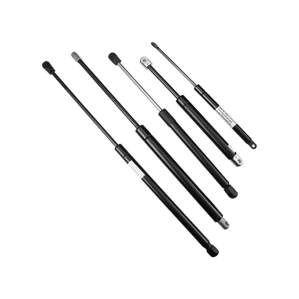
Managing heavy loads and kinetic energy is a daily reality on the shop floor and in mechanical design. When access panels, machine guards, or heavy hatches drop abruptly, you risk structural damage and severe operator injury. Uncontrolled motion causes shock loading. This accelerates component wear and fatigues hinges rapidly. Traditional mechanical coil springs fail here because they deliver variable force, lacking consistent resistance across the full range of motion. To fix this, engineers specify a Supporting Gas Spring. This component provides synchronized, damped, and predictable motion control. Whether you are lifting a heavy enclosure, lowering a protective cover, or holding a load securely, these units deliver precise kinematic control. They are the standard mechanism for demanding industrial and automotive applications, ensuring safety and operational reliability without overcomplicating the assembly.
Mechanism of Action: A supporting gas spring utilizes pressurized nitrogen for consistent force output and internal oil circuits for terminal damping, preventing abrupt end-of-stroke impacts and rapid, uncontrolled extension.
Specification Variables: Proper selection requires precise calculation of stroke length, extended length, load weight, and center of gravity to ensure optimal kinematic performance and secure holding force.
Application Versatility: From an automotive support strut to a mechanical equipment gas spring, specific use cases dictate the required seal materials, force curves, and mounting orientations.
Risk Mitigation & ROI: Incorrect mounting geometry or orientation leads to premature seal failure and loss of damping; adhering to manufacturer installation guidelines is critical for maximizing lifecycle ROI and reducing system-wide wear and tear.
Inside the cylinder, the architecture is straightforward but highly effective. You have a high-strength pressure tube, a micro-finished piston rod, a precision piston assembly, and a dynamic sealing system. Force generation comes entirely from pressurized nitrogen gas. We use nitrogen because it is inert. It does not react with internal components and remains stable under pressure. This gas pushes against the cross-sectional area of the piston rod, creating the outward extension force. The micro-finished piston rod is polished to an exact surface roughness. If the rod is too rough, it acts like sandpaper against the dynamic seal. If it is too smooth, it cannot carry the microscopic film of oil needed for lubrication.
Hydraulic oil sits inside this closed system to serve two distinct functions. First, it lubricates the main seal and guide block. This keeps friction low as the rod cycles in and out. Second, the oil controls the motion. The piston assembly contains a specific bypass channel. As the rod moves, nitrogen and oil flow through this channel. The diameter of this orifice dictates the flow rate. By restricting fluid transfer, the system controls the speed of extension and compression. You never want a rod firing outward uncontrollably, and this internal fluid dynamic prevents exactly that. The guide block keeps the rod perfectly centered as it strokes, while the dynamic sealing package usually consists of a primary lip seal and a secondary wiper seal to keep dust out.
If you look at the force delivery of mechanical coil springs, they follow Hooke's Law. The formula is F = kx, where force equals the spring constant multiplied by the displacement. The force they exert is directly proportional to how far you stretch or compress them. This creates a steep, linear force curve. You have to apply maximum manual effort at the start of a compression stroke. Then, the spring delivers aggressive, maximum force at full extension. Imagine lifting a 100-kilogram steel hatch. With a coil spring, the initial lift requires massive physical exertion. Once open, the spring tension is at its highest, putting immense stress on the hinges. This makes coil springs terrible for ergonomic lifting.
Gas springs operate differently. They provide a relatively flat force curve. The internal volume of the cylinder changes only slightly when the rod enters it. Therefore, the internal pressure stays mostly consistent throughout the entire stroke. Operators feel a uniform resistance when pulling a load down. They also get steady lifting support from the fully closed position all the way to the fully open state. With a gas-charged unit, that 100-kilogram load feels like 10 kilograms throughout the entire arc of movement. This flat curve reduces physical strain on the floor workers and keeps the load stable at any point.
Shock loading destroys equipment. When a heavy moving mass stops suddenly, it transfers kinetic energy straight into your hinges, brackets, and framework. Terminal damping eliminates this impact. Inside a standard unit, a small volume of hydraulic oil pools at the end of the cylinder near the rod exit.
As the rod reaches the final phase of its extension, the piston assembly leaves the nitrogen gas zone. It enters this hydraulic oil zone. Oil is much more viscous than nitrogen. It flows through the piston's bypass channel at a drastically slower rate. This sudden flow restriction gently decelerates the piston rod right before full extension. This action minimizes vibration and cuts out operational noise. More importantly, it stops mechanical stress from tearing your mounting points apart. Without this damping phase, the continuous metal-on-metal impact at the end of the stroke would shear the mounting studs within weeks.
Heavy hatches and access panels need specific kinematic profiles. The main goal is ergonomic access. A properly sized lifting gas strut gives you enough initial force to overcome the static friction and dead weight of a heavy lid. One operator should be able to open it without straining. For example, on a CNC machine enclosure, the operator needs to open the heavy polycarbonate door dozens of times a shift. If the door is too heavy, operator fatigue sets in, leading to mistakes. The strut takes the brunt of the load.
After the initial lift, the strut must hold the load securely in the open position. You cannot have accidental closures while someone is working inside the machine. You typically mount the strut so it pushes past the center of gravity when fully open, creating a mechanical lock. When closing, the strut provides controlled resistance so gravity does not slam the hatch shut. We achieve synchronized motion by installing paired struts. Both units must have identical force ratings and damping profiles. This keeps the lid level and prevents the hinges from binding.
Vehicles operate in harsh environments. Hoods, tailgates, and commercial storage compartments face constant abuse. An automotive support strut has to perform reliably despite road vibration, dirt, moisture, and wild temperature swings. Consider a heavy-duty commercial truck toolbox. The strut must survive years of slamming, chassis vibration, and exposure to corrosive de-icing chemicals on winter roads.
Environmental resistance is non-negotiable here. We treat the external cylinders with heavy-duty anti-corrosion coatings like electrophoretic deposition or thick powder coats. Automotive units undergo rigorous salt spray testing, often exceeding 500 hours, to prove their corrosion resistance. The internal seals use specialized elastomers that survive sub-zero winters and blistering engine bay heat. Automotive units also use custom damping profiles. They are designed to slow a heavy tailgate down right at the last few degrees of travel, giving you a smooth, premium closing action.
Industrial machinery demands extreme durability. Manufacturing equipment, medical imaging devices, and aerospace components run heavy loads at high frequencies. A mechanical equipment gas spring is built to handle this continuous operational stress. In a packaging plant, a diverter arm might cycle 500 times an hour. The internal seals must withstand the constant heat generated by this rapid friction.
These industrial versions use heavy-duty dynamic seals, reinforced guide blocks, and high-pressure cylinders. In automated setups, the travel speed must match the cycle times of the surrounding robotics. We use custom damping profiles so the moving machine guard accelerates and decelerates exactly as the programmable logic controller dictates. Building these springs robustly keeps the machines running and drastically cuts down on maintenance downtime.
You cannot guess the required Newton (N) force. It is not just about matching the total weight of the lid. You have to measure the weight, find the exact center of gravity, and measure the distance from that center to the hinge pivot point. This gives you the moment arm. Torque equals force times distance. The gas spring must generate enough torque to counter the torque generated by the lid's weight. If you move the mounting point just 10 millimeters closer to the hinge, the required force can double. This is why precision in your CAD model is non-negotiable.
We measure the force output at specific points along the stroke. These are F1, F2, F3, and F4. F1 is the extended force, measured right before full extension. F4 is the compressed force, measured right before full compression. The progression ratio between F1 and F4 matters immensely. A good ratio means the strut has enough force to lift the load from closed (F4) while keeping enough holding force (F1) to keep it open safely.
Force Progression Measurement Points
| Force Parameter | Measurement Location | Operational Impact |
|---|---|---|
| F1 (Extended Force) | 5mm before full extension | Determines holding capacity when fully open. |
| F2 (Initial Compression) | 5mm into compression stroke | Dictates manual effort to start closing. |
| F3 (Pushing Force) | 5mm before full compression | Force exerted just before complete closure. |
| F4 (Compressed Force) | 5mm after extension begins | Initial lifting assistance for heavy hatches. |
Different machines need different motion profiles. A heavy blast door might need to open fast but close slowly. A delicate instrument cover needs slow motion in both directions. We handle this by customizing the damping zones and speed control mechanisms. For instance, a hospital bed requires perfectly smooth, silent adjustment. Dual-direction damping ensures the bed raises and lowers without jarring the patient.
Extension damping is standard. It slows the rod as it reaches full length. Compression damping restricts fluid flow when you push the rod in, stopping heavy loads from dropping too fast. Dual-direction damping uses complex valving inside the piston to control speed both ways. By changing the physical size of the piston orifice, we fine-tune the exact travel speed. This ensures the motion matches your safety and operational specs perfectly.
The materials you choose dictate where the component can survive. Standard carbon steel cylinders work fine for dry, indoor shops. But marine decks, food processing lines, and semiconductor cleanrooms have strict compliance rules. In a meat processing facility, equipment is washed down daily with caustic chemicals. Standard steel would rust within a week, causing the pressurized gas to blow out. For those environments, we specify 316L stainless steel. It prevents oxidation, survives harsh chemical washdowns, and stops particulate shedding.
Ambient temperature also changes the force output. This follows Gay-Lussac's Law. When it gets hot, the kinetic energy of the nitrogen molecules increases. This raises the internal pressure and the output force. When it gets freezing cold, the pressure drops. If a machine operates in a cold storage facility at -20°C, the standard nitrogen charge will drop in pressure, causing the lid to sag. You must specify a higher initial charge pressure to compensate for extreme environments.
Incorrect mounting orientation is the number one reason these units fail in the field. We see this constantly. A contractor installs the unit upside down because it looks better or fits easier. Six months later, the seal dries out, the gas leaks, and the heavy door falls on someone's hand. The internal hydraulic oil must lubricate the primary dynamic seal where the rod exits the cylinder. If that seal dries out, friction spikes. You get micro-abrasions, the nitrogen gas leaks out, and the unit is dead.
To keep that seal lubricated, you must mount a standard unit rod-down. Gravity pulls the oil down to pool around the main seal. Rod-down mounting is also required for terminal damping to work. If you mount it rod-up, the piston never hits the oil zone at the end of the stroke. The rod will fire out rapidly without damping and rip your hinges right off the frame.
Side-loading destroys internal seals fast. These cylinders are built to handle axial loads, meaning forces applied straight down the length of the rod. When you have misaligned hinges or flexing panels, you introduce lateral forces. Think of a wide, flimsy fiberglass hood. As you pull it down from one corner, the hood twists. This twist translates directly into side-loading on the strut rod. It pushes the piston rod sideways against the guide block.
That lateral stress deforms the primary lip seal. It creates microscopic gaps, and your nitrogen gas escapes. To stop this, use the right mounting hardware. Only use rigid eyelet mounts if your system is perfectly aligned. If your pivot geometry shifts during travel, you must use ball joints or self-aligning mounting brackets. Use steel ball studs with retaining clips. Avoid cheap plastic end fittings in high-vibration environments because they will shatter. These articulating joints absorb the lateral stress, keeping the rod straight and the seals intact.
When outfitting high-cycle industrial machinery, you have to weigh the initial procurement costs against the operational lifespan. Standard commercial units have a lower upfront cost. They work perfectly for low-frequency access panels that you only open for occasional maintenance.
But in a continuous-duty manufacturing plant, standard units wear out quickly. You will face frequent replacements and machine downtime. Downtime on a primary manufacturing line can cost thousands of dollars a minute. Saving fifty dollars on a cheaper, standard-duty strut is a terrible engineering decision when it leads to a line stoppage. Heavy-duty variants use reinforced seals, thicker cylinder walls, and better internal lubrication. They cost more upfront. However, they deliver a significantly longer lifecycle. By absorbing kinetic energy consistently over millions of cycles, these heavy-duty units reduce wear on your expensive machinery. They extend operational longevity and stretch out your maintenance intervals.
To finalize your mechanical design and ensure safe, reliable motion control, execute the following steps:
Calculate the exact load geometry, including the center of gravity and moment arm, using manufacturer sizing software.
Specify the required seal materials and anti-corrosion coatings based on the peak temperature and environmental exposure of your application.
Select the appropriate damping profile (extension, compression, or dual-direction) to match the required cycle times of your machinery.
Request 3D CAD models from the supplier to run kinematic simulations and verify clearance within your assembly.
Order prototype units and conduct physical lifecycle testing on the shop floor before approving the final specification for mass production.
A: A mechanical coil spring follows Hooke's Law, delivering a variable force that increases linearly as it compresses. A supporting gas spring uses pressurized nitrogen to provide a flat, consistent force curve. It also contains hydraulic oil for terminal damping, enabling controlled lowering and shock prevention.
A: Force loss happens when pressurized nitrogen gas escapes the cylinder. This leakage is caused by micro-abrasions on the internal dynamic seals. Dust ingress, side-loading from misaligned hinges, and a lack of oil lubrication due to incorrect mounting orientation all accelerate this seal wear.
A: Generally, no. While they function similarly, industrial machinery requires different seal materials, reinforced guide blocks, and tighter force tolerances to survive continuous, high-frequency duty cycles. Automotive struts are built for lower cycle counts and specific environmental threats like road salt and extreme weather.
A: This is almost always due to incorrect installation. Standard units must be mounted rod-down. If mounted rod-up, gravity pulls the internal hydraulic oil away from the rod exit. The piston never travels through the oil zone at full extension, resulting in rapid, undamped movement.
A: You must determine the weight of the lid, locate its exact center of gravity, and measure the distance from the hinge to that center of gravity. This moment arm calculation dictates the required Newton force. Always use manufacturer specification software to ensure accurate sizing.
A: Yes. Following Gay-Lussac's Law, the internal nitrogen pressure changes by roughly 3.4% for every 10°C (18°F) shift in temperature. High heat increases the output force, while extreme cold decreases it. You must specify temperature-compensated units for environments with severe temperature fluctuations.


