

close
Choose Your Site
Global
Social Media

Author: Site Editor Publish Time: 2026-06-29 Origin: Site
Selecting a Controllable Gas Spring is a precise engineering decision where accuracy truly matters. Specifying the incorrect component often leads to premature seal failure, erratic positioning, or catastrophic load drops. Engineers frequently struggle to balance load force requirements against extremely tight spatial constraints. Failing to address these critical variables creates dangerous mechanical faults over time. Proper specification guarantees long-term safety, structural integrity, and smooth handling for operators. This guide bypasses basic definitions to explore exact calculation variables and intricate internal locking mechanisms. We focus heavily on the environmental constraints required to evaluate and shortlist the right components for medical, industrial, or ergonomic applications. You will learn how to perfectly match locking types to heavy dynamic loads. You will also discover how to mitigate severe side-loading risks through proper rod-down orientation and correct end fittings.
Match the locking type to the load: Differentiate between elastic, rigid-in-tension, and rigid-in-compression locking mechanisms based on safety requirements.
Calculate precise force (F1) and stroke: Over-specifying force creates user strain; under-specifying causes load failure.
Factor in environmental degradation: Temperature extremes and corrosive environments dictate seal materials and cylinder metallurgy (e.g., carbon vs. stainless steel).
Prioritize orientation and fittings: Eliminate side-loading risks by selecting the correct end fittings and adhering to rod-down installation protocols.
Engineers must first differentiate between simple assistance and infinite variable control. Standard components offer basic open-and-close push assistance. A standard gas spring strut pushes a load outward continuously without stopping. Conversely, controllable variations feature a highly engineered internal valve mechanism. This built-in valve allows infinite variable positioning anywhere along the stroke length. You press a release pin to open the internal bypass channel. Releasing this pin closes the valve and locks the rod firmly in place.
You must identify your primary objective early in the design phase. Ergonomic adjustments require entirely different setups than structural safety applications. Hospital beds and operator seating prioritize user comfort, shock absorption, and smooth dampening. Heavy access panels and aerospace compartments prioritize unyielding structural support under immense weight. Framing this business problem dictates every subsequent engineering choice.
A successful specification achieves three crucial mechanical targets. First, it ensures smooth and predictable actuation for the end user. Second, it delivers absolute zero-drift holding capacity under heavy static loads. Third, it guarantees a cycle life exceeding the parent product warranty period. We recommend explicitly defining these success criteria before calculating any physical dimensions. Establishing clear goals prevents costly over-engineering.
Calculating the required extension force (F1) demands precise load data. You must know the exact load weight and pinpoint its center of gravity. Mounting points on the moving flap and fixed frame dictate your mechanical advantage. Do not rely entirely on theoretical calculations for these figures. Theoretical formulas often ignore structural system friction and rod progression rates. These omissions cause frustrating specification errors during final assembly.
Under-specifying the internal force causes dangerous load failures and sudden drops. Over-specifying creates excessive user strain during the compression phase. You must define the exact travel distance your specific application needs. We refer to this required travel distance as the stroke length. Furthermore, you must balance the fully extended length against available physical space. The compressed state often limits your maximum allowable cylinder length. If the area is too tight, standard cylinders simply will not fit.
Internal pressure increases naturally as the rod enters the sealed cylinder. This internal volume reduction creates a natural progression ratio. You must specify whether your application requires linear or progressive force curves. High progression ratios make the final compression phase significantly harder to push. We suggest reviewing your kinematic mounting geometry to optimize this ratio. Adjusting pivot points can drastically smooth out the perceived user effort.
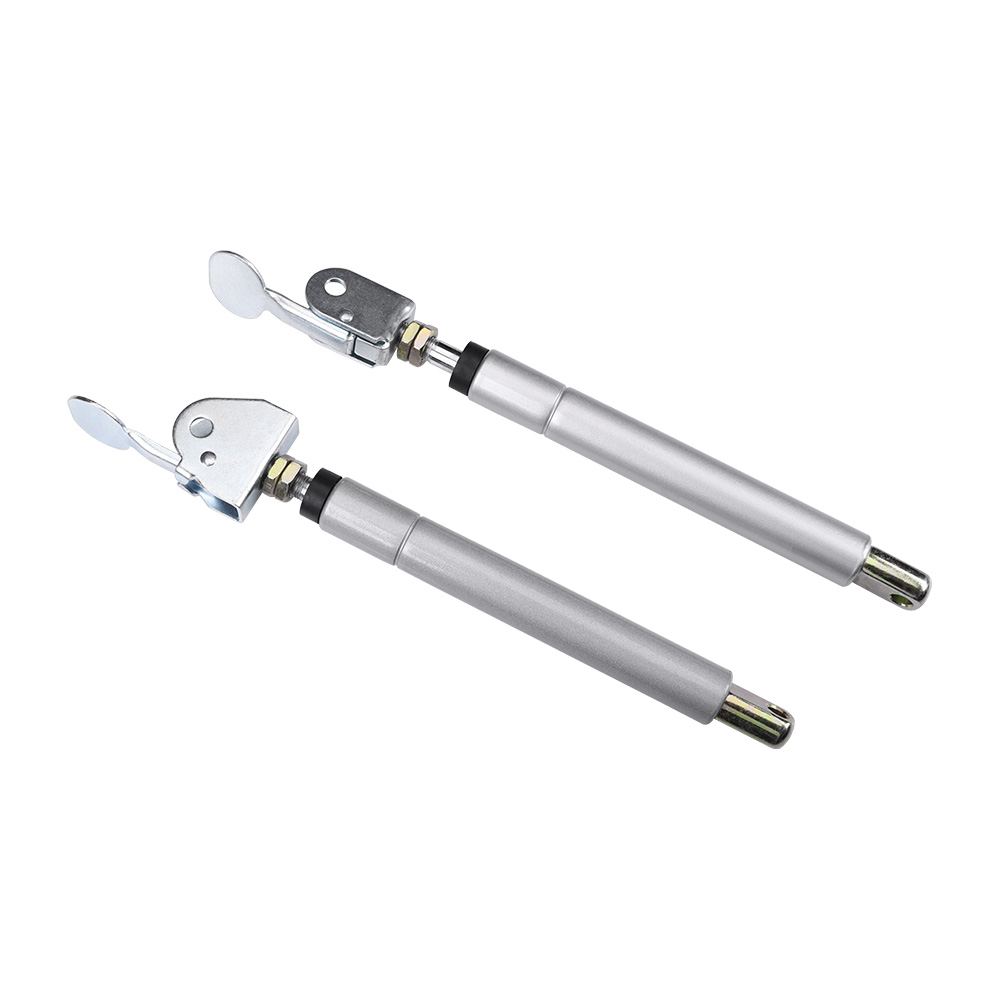
Choosing the correct locking type is critical for structural safety and user comfort. Elastic locking utilizes compressed nitrogen gas on both sides of the internal piston. Because gas remains compressible, this mechanism provides a springy, cushioned feel. It acts as an excellent shock absorber during sudden impacts. Applications requiring bounce, like ergonomic seating or light medical chairs, benefit immensely here. However, it cannot hold heavy structural loads rigidly.
Rigid locking in extension utilizes an incompressible oil chamber below the piston. This oil column prevents the rod from compressing inward when locked. Sudden heavy loads might hit an extended component unexpectedly. Medical operating tables and heavy industrial workbenches rely on this rigid support. The load will not drop or bounce, ensuring maximum stability.
Rigid locking in compression uses an oil chamber above the piston instead. This prevents the rod from extending outward when the valve is locked. Unintended extension poses massive safety hazards in specific scenarios. It serves perfectly for fail-safe structural holding on heavy access doors. We have outlined these primary locking types in the chart below for quick reference.
| Locking Mechanism | Internal Media | Primary Benefit | Ideal Application Scenarios |
|---|---|---|---|
| Elastic Locking | Compressed Nitrogen Gas | Provides cushioned shock absorption. | Ergonomic seating, light medical chairs, monitors. |
| Rigid in Extension | Oil Chamber (Below Piston) | Prevents compression under heavy load. | Medical tables, adjustable workbenches, heavy desks. |
| Rigid in Compression | Oil Chamber (Above Piston) | Prevents unwanted outward extension. | Heavy access panels, secure storage compartments. |
Operating temperature drastically affects internal pressure and main seal longevity. According to Gay-Lussac’s Law, internal gas pressure increases as ambient temperature rises. Standard nitrile rubber seals handle environments from -20°C to +80°C (-4°F to 176°F). Extreme heat or freezing cold degrades these standard seals rapidly. You must specify Viton or proprietary temperature seals for extreme outdoor environments. Failing to upgrade seals leads to sudden gas loss in the field.
Corrosion and chemical exposure dictate your cylinder and rod metallurgy choices. Standard carbon steel works perfectly well for dry indoor environments. However, marine environments, food processing plants, and medical cleanrooms demand superior chemical resistance. The cost premium of 316L stainless steel becomes easily justified here. Stainless steel prevents rust flakes from contaminating sterile environments or seizing the mechanism.
Surface treatments on the piston rod protect the internal seals from abrasion. Analyze your operating environment carefully before finalizing your surface metallurgy.
Nitride Coatings: Provide excellent wear resistance and a matte black finish. They handle standard industrial environments incredibly well.
Chrome Plating: Prevents micro-pitting and offers superior smoothness. This minimizes seal friction and prevents premature gas loss in high-cycle applications.
Epoxy Powder Coating: Applied to the outer cylinder for robust external rust protection.
The side-loading trap remains the single biggest killer of internal seals. Lateral forces push the rod against the cylinder wall during actuation. This causes immediate micro-abrasions on the main seal and rod surface. Catastrophic gas leakage follows shortly after this damage occurs. You must eliminate all side loads to preserve component life. Using articulating end fittings mitigates this severe mechanical risk entirely.
Selecting the correct end fittings ensures smooth, linear force delivery. Ball and socket joints serve best for absorbing minor structural misalignments. They grant multi-directional pivot freedom during the opening arc. Conversely, clevis or eyelet fittings serve best for heavy-duty applications. They handle strictly linear pivot motions perfectly but forgive zero lateral misalignment. Match the fitting strictly to your hinge tolerances.
Installation orientation dictates the lifespan of your chosen component. Always mount these units in a strict "rod-down" orientation. This operational necessity ensures internal oil constantly lubricates the main seal. Proper oil lubrication prevents dry-rot, reduces massive friction loss, and swells the seal tight. Installing the unit upside down guarantees premature dry friction and rapid failure.
Evaluating a supplier requires demanding verifiable testing data upfront. Do not accept theoretical lifecycle claims without physical testing documentation. Minimum testing benchmarks should sit comfortably between 50,000 to 100,000 cycles. Verify relevant ISO or DIN quality certifications before approving any vendor. High-quality manufacturing standards ensure consistent internal pressures across massive production batches.
Assess if the manufacturer offers robust internal customization capabilities. Adjustable release pins greatly improve final ergonomics for the end user. You might need specific valve flow rates to control the actuation speed. Quick-install "click and go" hardware drastically reduces assembly line time. Standardizing these elements streamlines your entire manufacturing process.
Request De-gassable Prototypes: Order units fitted with manual release valves.
Test in the Physical Assembly: Install them into your actual product frame.
Dial in the Exact Force: Bleed off gas manually until the movement feels perfect.
Record the Final Pressure: Send this dialed-in force requirement back to the manufacturer.
This prototyping method eliminates guesswork. You can fine-tune the exact user experience before committing to large-scale production runs.
Specifying the perfect component relies on a strict, methodical decision matrix. You must first calculate the exact load and determine the necessary stroke length. Next, select the proper locking type to match your safety requirements. Then, upgrade your environmental materials and seals to survive the intended workspace. Finally, finalize your mounting geometry to eliminate dangerous side-loading forces entirely.
Evaluating these engineering variables requires looking far beyond initial unit costs. You must prioritize cycle life, maintenance reduction, and mandatory safety compliance. A well-specified component prevents sudden structural failures and significantly enhances the end-user experience. Shortcuts during the specification phase always lead to costly field replacements.
Your immediate next step involves bridging the gap between theory and reality. We highly recommend engaging directly with a manufacturer's application engineer. Provide your 3D CAD models and all calculated load data. Request a tailored, de-gassable prototype to test inside your physical assembly. Physical testing remains the only way to guarantee absolute mechanical success.
A: A standard strut provides continuous pushing force to assist in opening or closing heavy loads. It does not stop mid-stroke. A controllable version features an internal valve and a release pin. This allows you to lock the stroke securely at any infinite position along its travel path.
A: Lifespan depends heavily on cycle frequency, environmental exposure, and strict adherence to rod-down mounting protocols. Quality units operating in standard environments easily average 50,000 to 100,000 actuations before seal degradation occurs.
A: Generally, no. These are highly pressurized, sealed vessels. Once an internal seal fails and nitrogen pressure is lost, you cannot repair it. The entire unit must be replaced immediately to maintain safety and compliance standards.
A: Installing the unit rod-up pulls the internal lubrication oil away from the main seal. This leads directly to dry friction, accelerated micro-abrasions, and premature nitrogen gas leakage. Always install rod-down to keep the seal lubricated.


