

close
Choose Your Site
Global
Social Media

Author: Site Editor Publish Time: 2026-08-28 Origin: Site
Poor equipment ergonomics directly impact operational efficiency across industrial and commercial sectors. Operators face daily physical fatigue and repetitive strain injuries from interacting with poorly designed machinery. These physical burdens escalate liability risks, increase absenteeism, and decrease overall productivity. Engineers constantly battle the challenge of designing heavy access panels, non-adjustable workstations, and rigid seating. These components often require manual force far exceeding occupational safety thresholds. Relying on sheer human strength is no longer a viable design strategy. You need a mechanical advantage. Specifying a precisely calibrated Gas Lift Strut offers a verifiable method to reduce manual handling force. This integration ensures controlled movement across various applications. It helps manufacturers meet stringent ergonomic compliance standards without overhauling entire structural designs. We will break down the mechanics, applications, and specification processes required to implement these components effectively.
Integrating a gas lift strut reduces the initial physical force required by operators, shifting the burden of heavy lifting from the user to the mechanical system.
Precise mounting geometry and force curve calculations are critical; improper specification leads to premature failure or ergonomic degradation.
Adjustable gas springs provide customizable height and angle positioning, essential for multi-user workstations, control panels, and seating applications.
Evaluating the trade-offs between standard gas struts, locking gas springs, and hydraulic struts is necessary to match the component to specific environmental, load, and damping requirements.
Beyond human ergonomics, gas struts provide a cost-effective way to reduce wear and tear on equipment hinges and structural components by preventing sudden impacts.
Defining ergonomic success requires measurable benchmarks. Keeping manual lifting forces below OSHA and NIOSH recommended weight limits is paramount for workplace safety. Equipment design must enable optimal working angles to prevent musculoskeletal disorders. A mechanical assist device achieves these goals by manipulating leverage and absorbing kinetic energy. You cannot simply bolt a spring onto a heavy door and expect perfect results; you must understand the internal physics driving the assistance.
The core physics rely on gas compression within a sealed cylinder. A high-strength steel cylinder contains pressurized nitrogen gas. A piston rod pushes into this chamber, compressing the gas further. As the rod enters the sealed tube, it displaces a volume of gas equal to the volume of the rod itself. This displacement reduces the available space for the nitrogen, causing the internal pressure to rise. Unlike traditional mechanical coil springs that offer linear resistance, the force in a nitrogen-charged cylinder increases progressively as it compresses. This internal pressure dynamic means the operator needs significantly less initial manual force to start moving a heavy load.
We must map this force curve directly to human biomechanics. When a heavy machine lid is fully closed, the user is in the worst possible mechanical position to lift it. The lower back and shoulders bear the maximum strain. The compressed cylinder provides its maximum assistance exactly at this point. As the lid opens and the user gains better mechanical leverage, the internal pressure decreases. This creates a smooth, consistent lifting experience that protects the operator from sudden strain.
Ergonomic Force Reduction at Various Opening Angles
| Lid Opening Angle | Operator Leverage | Cylinder Compression State | Mechanical Assistance Provided |
|---|---|---|---|
| 0 Degrees (Fully Closed) | Poor (High strain on lower back) | Fully Compressed (Maximum internal pressure) | Maximum (Lifts the bulk of the dead weight) |
| 45 Degrees (Half Open) | Moderate (Arms engaged, back straight) | Partially Extended (Pressure dropping) | Moderate (Balances the load weight) |
| 90 Degrees (Fully Open) | Excellent (Load rests on hinges) | Fully Extended (Minimum internal pressure) | Minimum (Holds the panel in place) |
Internal balance dictates the quality of movement. Nitrogen gas provides the active pushing force, but without regulation, the rod would shoot out violently. A small volume of oil sits inside the cylinder to provide damping. The internal piston mechanism features a small orifice that regulates how fast the gas and oil bypass the piston head as the rod extends or compresses.
As the rod nears full extension, the piston passes through the oil chamber at the end of the tube. Oil is denser than nitrogen gas, so it forces the piston to slow down. This end-of-stroke damping prevents jarring movements. It stops heavy lids from flying open and hyperextending hinges. This controlled deceleration protects the operator's wrists and shoulders from sudden impact forces. Furthermore, this smooth movement acts as a highly effective way to reduce wear and tear on equipment hinges, frames, and latches. By eliminating violent metal-on-metal impacts, the entire structural integrity of the equipment lasts longer.
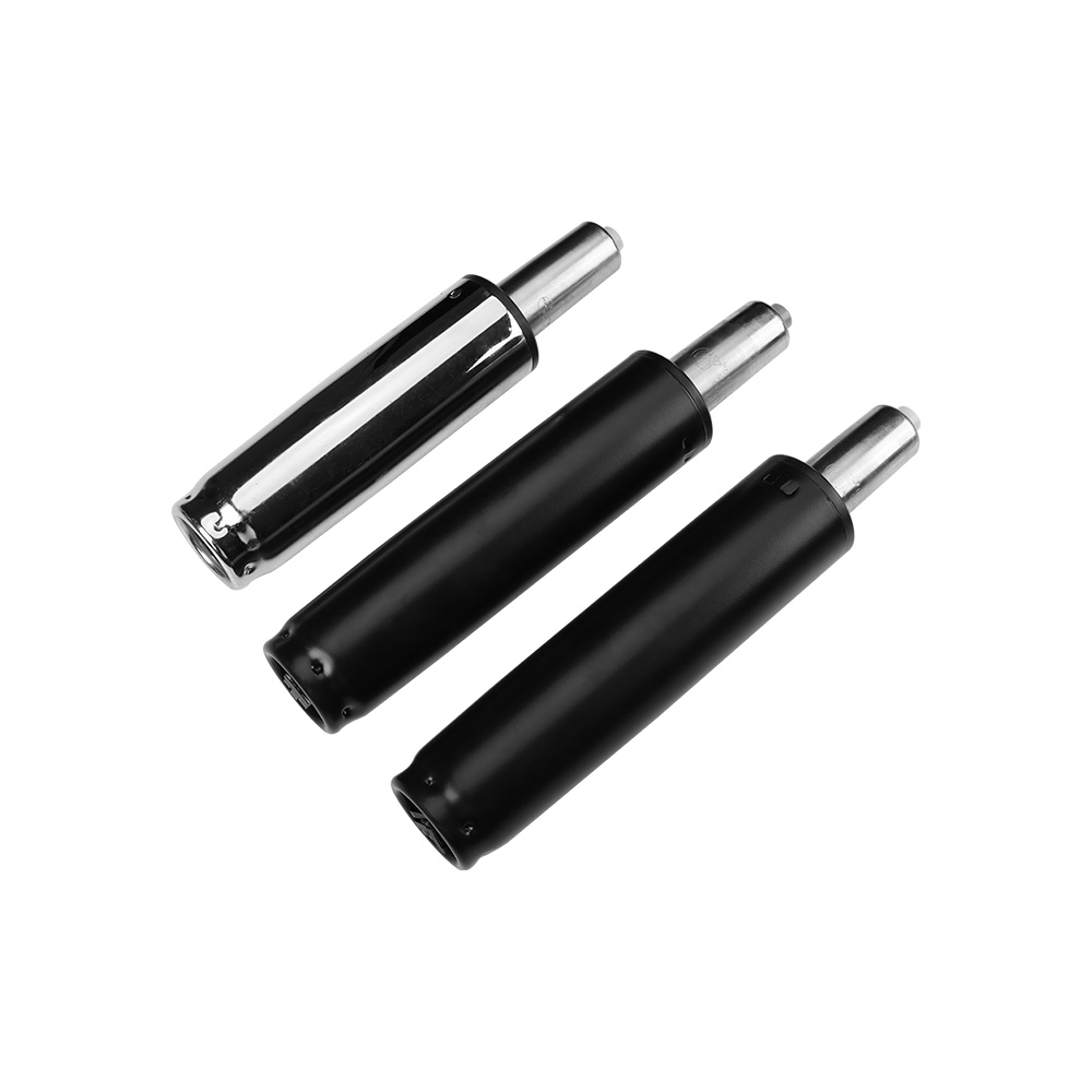
Different environments require specific mechanical solutions. Categorizing primary use cases helps identify where these components resolve specific ergonomic friction points most effectively. You will find these mechanisms deployed anywhere human operators interact with heavy, moving structural elements.
Heavy-duty manufacturing environments present severe ergonomic challenges. Operators frequently interact with heavy machine guards, large access panels, and dense tool covers. Lifting a solid steel CNC enclosure door manually multiple times a shift guarantees operator fatigue. Integrating a robust gas strut transforms a heavy steel door into a nearly weightless panel.
Enabling smooth, one-handed operation reduces unnecessary stretching. Back strain decreases dramatically for maintenance personnel who must access internal machine components. Furthermore, these devices allow operators to position control panels at comfortable viewing and typing angles. Awkward neck and shoulder postures disappear during prolonged shifts. The equipment adapts to the worker, rather than forcing the worker to adapt to the equipment.
Steps to Evaluate Heavy Machinery for Lift Assistance:
Identify all access panels weighing more than 25 pounds that require manual lifting.
Measure the frequency of access per shift to determine the cumulative ergonomic strain on the operator.
Assess the physical clearance around the hinges to ensure adequate space for mounting brackets and cylinder bodies.
Determine the maximum safe opening angle required for maintenance personnel to access internal components without obstruction.
Calculate the required holding force to keep the panel securely open during extended maintenance operations.
Multi-user environments demand extreme flexibility. Office chairs, hospital beds, over-bed tables, and laboratory drafting desks see constant use by people of varying heights and physical capabilities. An adjustable gas spring serves as the central mechanism for this adaptability. These specialized units feature an internal valve controlled by a release pin. When the user presses a lever, the pin depresses, opening the valve and allowing the piston to move freely. When the user releases the lever, the valve closes, locking the rod rigidly in place.
Seamless height and tilt adjustment allows users to customize their positioning instantly. A nurse can raise a medical bed to waist height, eliminating lower back strain during patient transfers. An office worker can adjust their chair to ensure their feet rest flat on the floor. Optimal posture, spine alignment, and visual ergonomics become achievable for every unique user interacting with the same piece of equipment.
The transportation sector relies heavily on ergonomic seating to prevent driver and passenger fatigue. Aircraft cabins and commercial vehicle seating utilize specialized lifting mechanisms. They provide reliable reclining capabilities and dynamic height adjustments. In these applications, failure is not an option, and the movement must be exceptionally smooth to convey a sense of quality and safety.
Long-haul truck drivers require seats that absorb road vibration while maintaining proper lumbar support. Aircraft passenger seats must recline smoothly without slamming into the passenger behind them. These components ensure controlled movement and adjustability, enhancing passenger and operator comfort during extended travel durations. The internal damping characteristics are heavily customized in aerospace applications to ensure the seat returns to the upright position slowly and quietly.
Selecting the correct component requires a strict engineering framework. You must map specific mechanical features to your desired ergonomic outcomes. Guessing the required force or mounting location will result in equipment that is either dangerous to operate or impossible to close.
Determining the required Newton (N) force is the most critical specification step. The calculation relies on the weight of the load, the distance to the center of gravity, and the precise location of the mounting points. You must calculate the moment arm to understand how much torque is required to lift the panel.
The standard industry formula for calculating the required force is: F = (W x L) / (d x n) + 10%. In this equation, W represents the weight of the flap or lid. L is the horizontal distance from the hinge to the center of gravity. The variable d represents the perpendicular distance from the hinge to the strut's mounting point. Finally, n is the number of struts you plan to use (typically two, one for each side to prevent twisting). The extra 10% acts as a safety margin to account for friction in the hinges and potential wind loading.
Over-specifying the force creates equipment that is incredibly difficult to close. The operator will have to hang their entire body weight on the lid to shut it, creating a new ergonomic hazard. Under-specifying means the mechanism fails to lift the load, requiring excessive operator exertion. A properly specified gas spring balances the load perfectly, allowing the panel to hover in place or open with minimal guidance.
The physical dimensions of the cylinder dictate the opening angle and ergonomic accessibility of the equipment. The stroke length determines how far the lid can physically open. If the stroke is too short, the operator might hit their head on the partially opened panel. You must select a cylinder with a stroke length that accommodates the full required range of motion.
The pivot point is equally critical. Slight adjustments in mounting geometry drastically alter the perceived weight by the user. Moving the mounting bracket just five millimeters closer to the hinge changes the entire leverage profile, requiring significantly more force from the cylinder to hold the lid open. Engineers must use kinematic modeling to find the optimal mounting locations that provide the best mechanical advantage throughout the entire range of motion. You want the strut to push past the center point when closed, actively holding the lid shut, and then smoothly take over the lifting burden as the operator opens it.
Engineers must choose between pneumatic and hydraulic systems based on the primary function of the equipment. Pneumatic variants utilize compressed nitrogen. They excel at lifting, holding, and assisting human movement. They act as a counterbalance to heavy weights, making them the standard choice for most ergonomic access panels and seating adjustments.
Conversely, a hydraulic strut relies entirely on fluid dynamics. It is better suited for heavy damping, shock absorption, and strict velocity control. It does not actively push a load open; it resists movement to control speed. You will see these used on heavy industrial gates or blast doors where preventing a rapid slam is more important than assisting the lift. You must evaluate maintenance requirements, cycle life, and performance in extreme temperatures for both options to ensure long-term ergonomic reliability.
Pneumatic vs. Hydraulic Component Specifications
| Feature | Pneumatic Variant | Hydraulic Variant |
|---|---|---|
| Primary Function | Lifting, assisting, and counterbalancing loads | Velocity control, shock absorption, and heavy damping |
| Internal Medium | Pressurized nitrogen gas with a small oil volume | 100% hydraulic fluid |
| Temperature Sensitivity | High (Force fluctuates with ambient temperature) | Low to Moderate (Viscosity changes affect speed) |
| Ideal Application | Access panels, ergonomic seating, machine guards | Heavy doors, industrial dampers, automated gates |
| Operator Exertion | Significantly reduced during lifting phases | Requires manual force to move, but prevents runaway speed |
Integrating these components introduces specific real-world challenges. Addressing adoption risks early in the design phase prevents costly field failures and ergonomic degradation. A poorly installed cylinder will fail prematurely, leaving the operator to deal with the full dead weight of the equipment.
Ambient temperature directly affects internal gas pressure based on Gay-Lussac's Law. As temperature drops, the gas condenses, and the lifting force decreases. You can expect roughly a 3.4% force change for every 10°C shift in ambient temperature. A heavy tractor hood calibrated perfectly for a warm factory floor will feel incredibly heavy to a farmer opening it in freezing winter conditions. Conversely, a panel calibrated in the winter will fly open aggressively in the summer heat.
Mitigate this risk for outdoor or extreme-environment equipment by specifying a slightly higher initial pressure to account for winter drops. Alternatively, utilize temperature-compensating valves or dynamic mounting brackets that allow users to adjust the leverage point based on seasonal temperature shifts. Moving the mounting point slightly further from the hinge in the winter gives the cylinder better leverage to overcome the pressure drop.
Internal seals degrade over time. Dust, debris, lateral loading, and improper mounting orientation accelerate this wear. If the rod bends even slightly due to lateral stress, the seal will break, and the pressurized nitrogen will escape. You must ensure the mounting brackets align perfectly so the cylinder only experiences linear compression and extension.
You must recommend specific mounting orientations. Always mount the cylinder with the rod pointing down in the resting position. This keeps the internal oil resting against the main seal. It keeps the seal lubricated, prevents it from drying out, extends the operational lifespan, and maintains consistent ergonomic performance over thousands of cycles. If you mount it rod-up, the seal dries out, cracks, and vents the nitrogen gas within a few months of use.
Sudden pressure loss poses severe safety risks in critical applications. If a seal blows out while an operator is standing under a heavy industrial hood, the panel will collapse instantly. The same risk applies to medical tables supporting patients or heavy aerospace cargo doors.
Evaluate the integration of locking tubes or locking mechanisms for overhead applications. A mechanical locking shroud drops into place when the rod fully extends, physically preventing the cylinder from compressing until the operator manually releases it. This ensures absolute operator safety and prevents catastrophic injuries during maintenance or daily use. For seating and medical beds, internal locking valves ensure the cylinder remains rigid even if the primary seal begins to leak slowly.
Measure the exact weight of your access panel and locate its center of gravity before selecting any hardware.
Calculate the required Newton force using the standard kinematic formula to ensure you do not over-specify or under-specify the lifting capacity.
Design your mounting brackets to allow for slight positional adjustments, enabling you to fine-tune the leverage point during final assembly.
Order physical prototypes with varying pressure ratings and conduct real-world ergonomic testing with actual operators to verify the lifting feel.
A: The terms are largely interchangeable in the manufacturing industry. However, "strut" often implies a structural or automotive application, like a vehicle tailgate. "Spring" typically implies a general lifting, pushing, or counterbalancing mechanism used in furniture or industrial machinery.
A: You must determine four primary variables. Measure the total weight of the lid. Find the exact distance from the hinge to the lid's center of gravity. Measure the distance from the hinge to your planned mounting point. Use these variables to calculate the required torque and resulting Newton force.
A: Adjustable models often feature a release valve that allows you to vent gas to lower the force. However, once vented, they cannot easily be re-pressurized in the field. Standard sealed units cannot be re-pressurized at all and must be replaced if they lose force.
A: Premature failure usually stems from three causes. Lateral stress bends the rod and breaks the seal. Incorrect mounting orientation (rod facing up) causes the internal seal to dry out and crack. Finally, exceeding the manufacturer's recommended cycle limits degrades the internal components.
A: Temperature directly impacts the internal nitrogen pressure. Force increases in high heat and decreases in extreme cold. Expect a force change of approximately 3.4% for every 10°C change in ambient temperature. This significantly impacts the lifting capacity of outdoor equipment.
A: A high-quality industrial unit typically lasts between 40,000 and 100,000 cycles. However, this lifespan depends entirely on the application, environmental conditions, proper mounting orientation, and the absence of lateral forces or abrasive dust on the rod.


