

close
Choose Your Site
Global
Social Media

Author: Site Editor Publish Time: 2026-10-25 Origin: Site
Heavy machinery doors often slam with tremendous force. This causes severe equipment damage and creates hazardous environments for floor workers. Uncontrolled kinetic energy is a persistent enemy of mechanical longevity. It slows down daily production and drives up maintenance costs across the plant floor. Resolving these destructive forces requires more than just bolting on heavier hinges. It demands precise, engineered fluid resistance.
A hydraulic gas-charged mechanism solves this problem by offering exact control over heavy moving masses. By balancing fluid dynamics with compressed inert gases, these components transform dangerous, erratic movements into smooth operations. In this comprehensive guide, we will break down the underlying mechanics of these systems, explore their real-world industrial applications, and show you how to specify the exact component for your machinery.
Hydraulic gas systems provide controlled, smooth motion by combining pressurized nitrogen gas for lifting force and hydraulic oil for end-of-stroke damping.
Integrating these components into industrial equipment significantly reduces impact shock, protecting hinges and extending the overall lifespan of the machinery.
Reliable lift supports are essential for workplace ergonomics. They ensure operators can manipulate heavy access panels safely and with minimal physical effort.
Selecting the right component requires precise calculation of stroke length, load capacity, and a thorough understanding of the operating environment.
Compared to traditional mechanical coil springs, gas-charged struts offer a flatter force curve, a more compact design, and superior deceleration capabilities.
Before diving into complex motion control systems and load calculations, we need to establish a clear understanding of the foundational technology. A highly engineered mechanical component designed to lift, hold, and counterbalance heavy objects operates very differently from traditional wire springs. Unlike standard coils that rely entirely on the physical deformation of metal, these advanced devices utilize compressed gas and fluid dynamics to generate and regulate force.
To comprehend how these components deliver consistent performance under extreme industrial stress, one must examine their internal architecture. A standard unit consists of several critical elements working in unison. The primary housing is a robust, seamless pressure tube, often manufactured from treated steel or stainless steel, designed to withstand immense internal pressures. Inside this cylinder operates the piston and piston rod, which extends and retracts based on the applied load.
The piston head itself is a marvel of micro-engineering. It contains specific orifices and valving systems that dictate the flow of internal fluids. To keep the system viable over thousands of cycles, a complex sealing system featuring heavy-duty guide bushings and O-rings traps the pressurized nitrogen gas inside. Furthermore, this seal package actively prevents external contaminants, like metallic dust or moisture, from entering the chamber. Finally, a specific volume of hydraulic oil rests inside the cylinder to lubricate the seals and provide essential hydrodynamic resistance.
The operational principle of these devices represents an elegant application of physics. When the piston rod is pushed into the cylinder during compression, the internal volume decreases. This action further compresses the inert nitrogen gas, storing massive amounts of potential energy. When the external mechanical load is released, the pressurized nitrogen naturally attempts to expand. This pushes the piston rod outward to provide the necessary lifting force.
However, generating brute force is rarely enough for sophisticated industrial equipment. Regulating the speed of that force is equally critical. This is where a high-quality damping gas spring becomes invaluable on the assembly line. As the piston rod nears full extension, the piston head plunges into the internal hydraulic oil zone. Because oil is significantly more viscous than nitrogen gas, it resists being forced through the microscopic orifices in the piston. This hydrodynamic resistance causes the extension speed to slow down dramatically just before reaching the end of the stroke. Consequently, this dual-action mechanism prevents heavy steel doors from flying open aggressively and ripping their hinges from the machine frame.
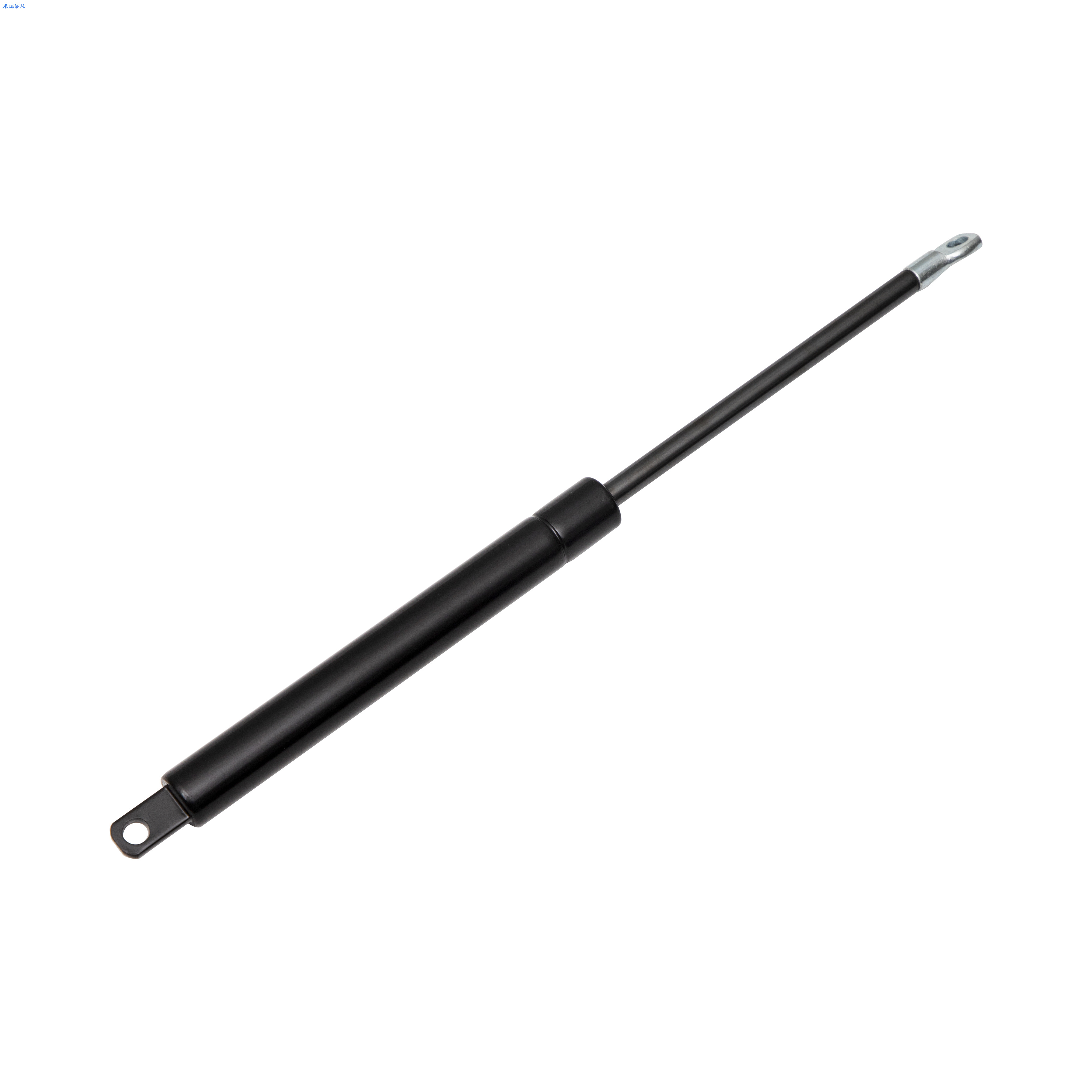
In modern industrial environments, machinery operates under punishing conditions. Equipment endures high cycle rates and massive structural loads daily. Therefore, motion control is not merely a matter of operational convenience; it is a fundamental engineering requirement.
Looking at current industry trends, the acceleration of Industry 4.0 has created a massive shift toward fully automated, high-speed manufacturing environments. Industry analysts consistently note that predictive maintenance and component longevity are now top priorities for plant managers worldwide. Erratic mechanical movements are simply no longer tolerated on the factory floor. This demand for reliability is driving a rapid transition from rudimentary mechanical hinges to advanced fluid motion control systems. Automated production lines rely on absolute mechanical precision and cycle consistency. If a protective enclosure opens too slowly, it delays the entire manufacturing cycle. Conversely, if it opens too quickly, it can bounce out of position and misalign sensitive optical sensors.
Properly engineered motion control impacts three major areas of an operation. First, it directly addresses operator safety and ergonomics. Industrial access panels and machine guards are often constructed from heavy-gauge steel or thick polycarbonate. If these components are not properly counterbalanced, they pose a severe crushing hazard. Proper counterbalancing neutralizes this weight, ensuring compliance with strict occupational safety standards and drastically reducing musculoskeletal injuries among workers.
Finally, uncontrolled kinetic energy destroys structural durability. When a heavy machine lid slams shut, the impact shock transfers directly into the frame and sensitive internal electronics. Over time, this repetitive stress causes metal fatigue, cracked welds, and premature equipment failure. By controlling deceleration, hydraulic systems absorb this energy and drastically reduce maintenance downtime.
Engineers consistently choose gas-charged hydraulic technology over other motion control methods because it offers a unique combination of benefits. These advantages are specifically tailored to address the harsh realities of industrial environments.
The most significant advantage is the built-in deceleration profile. Imagine a technician opening a 300-pound engine cowl on a mining excavator. The cowl may start moving quickly, but as it reaches the end of its travel path, the internal oil creates a cushioning effect. This hydraulic damping prevents the jarring stops that typically cause structural damage. By altering the internal valving, manufacturers can customize this damping profile to be fast, slow, or variable depending on the specific application.
Human operators simply cannot safely manipulate massive steel covers without mechanical assistance. Integrating a reliable hydraulic lift support transforms a dangerous physical task into a smooth, effortless motion. By calculating the exact center of gravity and the weight of the load, engineers can specify a unit that perfectly counterbalances the hatch. This makes a heavy lid feel virtually weightless to the end-user.
Traditional mechanical coil springs obey Hookes Law, meaning their force output drops linearly and rapidly as they expand. A gas-charged cylinder operates entirely differently. Because the internal volume of the cylinder is relatively large compared to the volume of the piston rod entering it, the internal pressure changes very little as the rod extends. This results in a flat force curve. The component provides a steady, consistent lifting force throughout the entire range of motion, ensuring a heavy lid does not suddenly drop when it is only halfway open.
Industrial equipment like heavy-duty presses, generators, and vibratory feeders generate massive amounts of kinetic energy. A standard mechanical hinge will rattle and degrade rapidly under these conditions. The compressed nitrogen inside a sealed cylinder acts as a pneumatic cushion against sudden impacts, while the oil dampens resonant frequencies. This stabilizes protective covers and prevents them from vibrating loose during operation.
Industrial applications often require fine-tuning during the prototype phase. Adjustable models feature a specialized release valve at the base of the cylinder. Engineers can order a unit charged to its maximum pressure, install it on the machine, and slowly vent the nitrogen gas using a specialized tool until the exact desired motion profile is achieved. This level of on-site customization is completely impossible with solid mechanical springs.
The versatility of fluid and gas motion control means these components are integrated into nearly every sector of heavy industry. Understanding specific use cases helps equipment designers visualize how to implement these solutions effectively in their own projects.
In the agricultural, construction, and mining sectors, equipment like tractors and wheel loaders feature massive engine compartments. Maintenance crews require quick, safe access to these engines in rugged, unpredictable environments. A heavy-duty hydraulic strut is utilized to lift these heavy metal hoods effortlessly and hold them securely in the open position, even in high winds or when the vehicle is parked on a steep incline.
Modern Computer Numerical Control machines and automated robotic cells are fully enclosed to protect workers from flying debris and laser radiation. The doors to these enclosures must open and close smoothly hundreds of times a day. Hydraulic motion control ensures these automated doors operate with absolute precision, without bouncing or slamming, which could disrupt the machining process or damage expensive tooling.
In industrial control rooms, operators have different ergonomic needs. By utilizing these components, equipment designers can create height-adjustable industrial desks, tilting monitor mounts, and articulating control panels. This allows operators to reposition heavy human-machine interfaces with a single hand, reducing fatigue and improving workplace efficiency across long shifts.
When engineering industrial equipment, designers frequently face a critical choice. They must decide between utilizing traditional mechanical coil springs or upgrading to a modern hydraulic system. While mechanical springs have been the historical standard, they rely entirely on the physical deformation of metal. In contrast, fluid and gas systems utilize compressibility and viscous resistance.
| Performance Vector | Traditional Mechanical Coil Springs | Hydraulic Gas Systems |
|---|---|---|
| Space Efficiency | Low. Requires significant physical size and thick wire diameters to generate high force. | High. A compact cylinder contains highly pressurized gas, delivering massive force in a minimal footprint. |
| Speed Control & Damping | None. Extension and compression speeds are uncontrolled, leading to jarring impacts. | Excellent. Built-in fluid regulates the piston speed, providing smooth end-of-stroke deceleration. |
| Force Curve Profile | Steep. Force drops rapidly as the spring extends, resulting in a linear loss of energy. | Flat. Maintains a highly consistent force output throughout the entire stroke length. |
| Environmental Protection | Poor. Open coils are susceptible to dust, debris, and physical jamming. | Excellent. The internal mechanism is fully enclosed and sealed against external contaminants. |
| Maintenance Requirements | High. Requires frequent lubrication and is prone to metal fatigue and sagging. | Low. Self-lubricating internal seals require minimal intervention if installed correctly. |
Analyzing these vectors reveals stark operational differences. In heavy machinery, internal space is often at a premium. Mechanical springs require a large physical volume to store sufficient potential energy. Conversely, by altering the initial nitrogen pressure inside a cylinder, manufacturers can achieve significantly higher load capacities within the exact same dimensional footprint.
Furthermore, coil springs are subject to severe metal fatigue. Over thousands of cycles, the metal structure weakens, resulting in a loss of lifting force. This phenomenon is known as spring sag. High-quality sealed systems do not suffer from metal fatigue in the same way. Assuming the seals remain intact and the operating temperature remains within specified limits, the nitrogen gas retains its pressure consistently over a lifespan that can easily exceed 100,000 cycles.
Specifying the correct motion control component is not a matter of guesswork; it requires precise mathematical calculation. Selecting an underpowered unit leads to heavy, unsafe doors, while an overpowered unit can make equipment impossibly difficult to close, placing undue stress on mounting points.
The lifting force is measured in Newtons. To determine the exact force required to lift a pivoting load, engineers must evaluate the weight of the load, the center of gravity, and the mounting geometry. The standard empirical formula used in the industry involves multiplying the mass of the door by gravity and the horizontal distance from the hinge to the center of gravity, then dividing that by the perpendicular distance from the hinge to the mounting point.
A safety margin of 10 to 15 percent is typically added to account for friction, wind resistance, or potential snow loads on outdoor equipment. Additionally, the stroke length, which is the total distance the piston rod travels, must be perfectly matched to the required opening angle. For context, standard units often feature stroke lengths ranging from 50mm up to 1000mm, with force capacities easily reaching 2500 Newtons. Choosing a high-quality industrial gas spring ensures that these calculations translate accurately into real-world performance, providing just enough force to lift the load smoothly without overpowering the user.
When defining specifications, buyers must choose between fixed-force and adjustable-force models. Fixed-force units are pressurized to a specific Newton rating at the factory. They are ideal for mass OEM production where the exact weight and dimensions of the moving load are consistent and thoroughly tested. They offer high reliability and a lower per-unit cost at scale.
Adjustable models, on the other hand, are supplied charged to their maximum pressure. During the prototyping phase, or in applications where the weight of the load might vary, an engineer can use a release tool to carefully vent small amounts of nitrogen. This allows for precise, on-site tuning of the lifting force.
The operational environment dictates the material construction and the type of internal seals required. For marine equipment, chemical processing plants, or outdoor agricultural machinery subjected to harsh washdowns, standard steel cylinders will degrade rapidly. In these scenarios, specifying 316L stainless steel is mandatory to prevent rust and maintain structural integrity.
Temperature extremes also play a critical role. Standard units operate efficiently between -20 degrees Celsius and +80 degrees Celsius. If the equipment is deployed in extreme cold like arctic mining, or extreme heat near industrial furnaces, standard Nitrile rubber seals will harden and fail. Engineers must specify special low-temperature seals or high-temperature Viton seals to prevent gas leakage.
Even the highest-quality motion control component will fail prematurely if installed incorrectly. Proper orientation and mechanical alignment are the most critical factors in maximizing the cycle life of these systems.
The most common installation error is mounting the unit upside down. Unless a specific internal design dictates otherwise, a hydraulic cylinder should almost always be installed with the piston rod pointing downward between 15 and 90 degrees from the horizontal when the component is in its resting or closed position.
This orientation is strictly related to the internal tribology of the system. The small volume of oil inside the cylinder must pool at the bottom, resting directly against the main seal. This keeps the rubber seal constantly lubricated, preventing it from drying out and cracking. Furthermore, as the rod extends downward, the piston moves through this oil pool just before reaching full extension, activating the vital damping effect that ensures a shock-free stop.
These components are designed exclusively to handle axial loads, which are forces applied directly along the straight line of the piston rod. They are not structural load-bearing components designed to handle lateral or side-to-side bending forces.
If the mounting points on the equipment are misaligned, bending forces are transferred directly to the piston rod. This causes the rod to press unevenly against the internal seal and the guide bushing. Over time, this asymmetrical friction will score the metal rod and warp the seal, leading to rapid gas loss. To mitigate this, engineers should utilize ball socket joints or swivel clevis brackets. These articulating end fittings provide a few degrees of rotational freedom, absorbing minor structural misalignments.
Maintenance is generally minimal, but the condition of the piston rod is paramount. The rod is typically treated with a hard chrome or QPQ finish to provide a microscopically smooth surface. It should never be scratched, dented, or painted. Painting the equipment and accidentally over-spraying the piston rod will cause the dried paint to tear the internal seal as the rod retracts.
When cleaning industrial machinery, operators must never use abrasive pads, wire brushes, or harsh acidic chemicals on the piston rod. A simple wipe with a clean, damp, non-abrasive cloth is entirely sufficient to remove industrial dust without compromising the seal.
Integrating advanced hydraulic motion control into industrial equipment is a highly effective way to improve machine safety and operational efficiency. By leveraging the physical properties of compressed nitrogen and viscous fluid, these components turn dangerous, erratic mechanical movements into controlled, ergonomic operations.
Choosing the right component extends equipment lifespan by eliminating the structural shock that destroys hinges and frames. By carefully evaluating your load capacity, stroke requirements, and environmental conditions, you can protect your workers from injuries and drastically reduce maintenance downtime. When you are ready to upgrade your machinery's motion control, sourcing reliable components is critical. Visit Mirui Gas Spring at https://www.miruigasspring.com to explore a full catalog of engineered solutions and find the exact match for your specific load and stroke requirements.
While they may look identical externally, their internal functions differ significantly. A gas spring contains highly pressurized nitrogen gas, which actively exerts a pushing or pulling force to lift or support a load, combined with a small amount of oil for end-stroke damping. A pure hydraulic damper contains no pressurized gas; it is filled entirely with oil. Therefore, a damper provides no lifting force. It only provides viscous resistance to control the speed of a moving mass that is being driven by another force, such as gravity or a mechanical motor.
The lifespan is heavily dependent on the application cycle rate, operating temperature, and strict adherence to installation best practices. Under optimal conditions, with correct rod-down orientation, clean environments, and zero side-loading, a high-quality unit can reliably perform between 40,000 and 100,000 complete extension and compression cycles before the internal seals naturally degrade and pressure is eventually lost.
Standard fixed-force models are permanently sealed at the factory and cannot be adjusted or refilled by the user. However, adjustable models feature a specialized bleed valve at the base. This allows operators to carefully release nitrogen gas to reduce the lifting force if it is too strong for the application. It is important to note that once the gas is vented, it cannot be refilled by the end-user without specialized factory pressurization equipment.
The vast majority of premature failures are caused by mechanical misalignment resulting in side-loading. When lateral forces bend the piston rod, it creates uneven wear on the internal seal, allowing the pressurized nitrogen to leak out. Other common causes include physical damage to the rod like deep scratches, weld spatter, or accidental paint coverage, installing the unit rod-up which dries out the seals, and exposing standard rubber seals to extreme temperatures beyond their rated limits.
To calculate the required force, you need to know the weight of the door, the distance from the hinge to the door's center of gravity, and the distance from the hinge to the gas spring mounting point. You multiply the door weight by the center of gravity distance, then divide that number by the mounting point distance. Finally, engineers typically add a 10 to 15 percent safety margin to account for hinge friction and external environmental factors.
Standard industrial units utilizing Nitrile rubber seals are designed to operate efficiently between -20 degrees Celsius and +80 degrees Celsius. Operating outside of this range will cause standard seals to either harden and crack in the cold or degrade rapidly in the heat. For extreme environments, manufacturers can equip the cylinders with specialized low-temperature seals or high-temperature Viton seals to maintain pressure integrity.


