

close
Choose Your Site
Global
Social Media

Author: Site Editor Publish Time: 2026-08-15 Origin: Site
The mechanical success of any lifting or dampening application relies entirely on the geometric relationship between the pivot point, the load, and the mounting angle of the support mechanism. Engineers often face situations where heavy lids, access panels, or protective covers fail to operate smoothly despite utilizing high-force components. This failure rarely stems from a lack of lifting power. Instead, it originates from improper geometric alignment during the design phase.
Incorrect mounting geometry introduces severe operational costs and safety risks. When angles are miscalculated, the system experiences premature seal failure, excessive hinge stress, erratic damping, and the complete inability to hold loads safely in the open position. A common misconception in mechanical design is that purchasing a higher-force unit will compensate for poor angular positioning. In reality, excessive force applied at the wrong angle only accelerates structural fatigue and hinge binding.
Resolving these mechanical issues requires calculating precise mounting angles and understanding internal fluid dynamics based on physical orientation. Utilizing these metrics allows fabricators to evaluate and specify the correct hardware for commercial applications. By mastering the relationship between moment arms and force vectors, you can ensure smooth, predictable motion control across any technical project.
Orientation Dictates Lifespan: Mounting a gas strut in a "rod-down" position ensures internal oil continuously lubricates the main seal and provides consistent end-of-stroke damping.
The 1/3 Rule Establishes the Baseline: Optimal mechanical advantage typically begins by positioning the moving mounting point approximately 33% of the lid’s total length away from the hinge.
Angles Alter Force Vectors: A strut mounted vertically when closed offers a superior force response curve compared to acute horizontal angles, reducing the initial lifting force required by the user.
Velocity-Dependent Resistance: Changing the mounting angle alters the piston speed through its stroke; higher piston velocities generate exponentially higher hydraulic resistance, demanding precise geometric alignment.
Prototyping Requires Flexibility: Utilizing an adjustable gas spring during the initial design phase mitigates the risk of miscalculating the required force for complex mounting angles.
Integrating a lifting mechanism requires defining clear success criteria for the physical application. The primary goal is achieving a balanced, ergonomic lift with minimal user exertion, smooth transit throughout the entire stroke, and zero hinge binding. When a user opens a heavy panel, the initial lift should feel light, and the motion should remain controlled without requiring excessive pushing or pulling. Achieving this balance depends entirely on how the force vectors interact with the load's center of gravity.
The angle of the support relative to the lid directly alters the effective moment arm. The moment arm is the perpendicular distance from the pivot point to the line of action of the force. As the angle changes throughout the stroke, the lifting force exerted on the center of gravity fluctuates dynamically. If the moment arm is too short during the initial opening phase, the user must overcome the full dead weight of the lid. As the lid opens and the angle increases, the moment arm lengthens, multiplying the effective lifting force. This dynamic shift explains why doors sometimes fly open violently if the geometry is incorrect.
Industry standards dictate maintaining a 10° to 30° angle from the fully closed position. This specific angular range prevents the mechanism from pushing directly into the hinge. Pushing laterally into the hinge pivot causes mechanical lock-up, making the door nearly impossible to open while placing immense shear stress on the fasteners. A 10° to 30° offset ensures enough vertical force vector remains to initiate the opening sequence smoothly without overloading the pivot hardware.
Verifying this angle in physical prototypes prevents costly manufacturing errors down the line. Fabricators rely on practical methods for in-situ angular measurement. Digital inclinometers or smartphone-based angle measurement applications provide immediate feedback on the shop floor. By measuring the closed and open angles directly on the physical prototype, engineers can confirm that the actual physical angles perfectly match the theoretical design files, ensuring the calculated force vectors behave as intended.
To properly measure and verify these angles in the field, follow these practical steps:
Position the lid or panel in its fully closed state and secure it temporarily.
Place a digital inclinometer directly on the mounting bracket surface to establish a zero reference point.
Measure the angle of the proposed cylinder path relative to the hinge pivot line.
Open the panel to its maximum required extension and support it safely with a mechanical prop.
Recalculate the angle at full extension to ensure it does not exceed the physical limits of the ball studs or mounting hardware.
Adjust the lower mounting bracket position until the closed angle falls strictly within the 10° to 30° range.
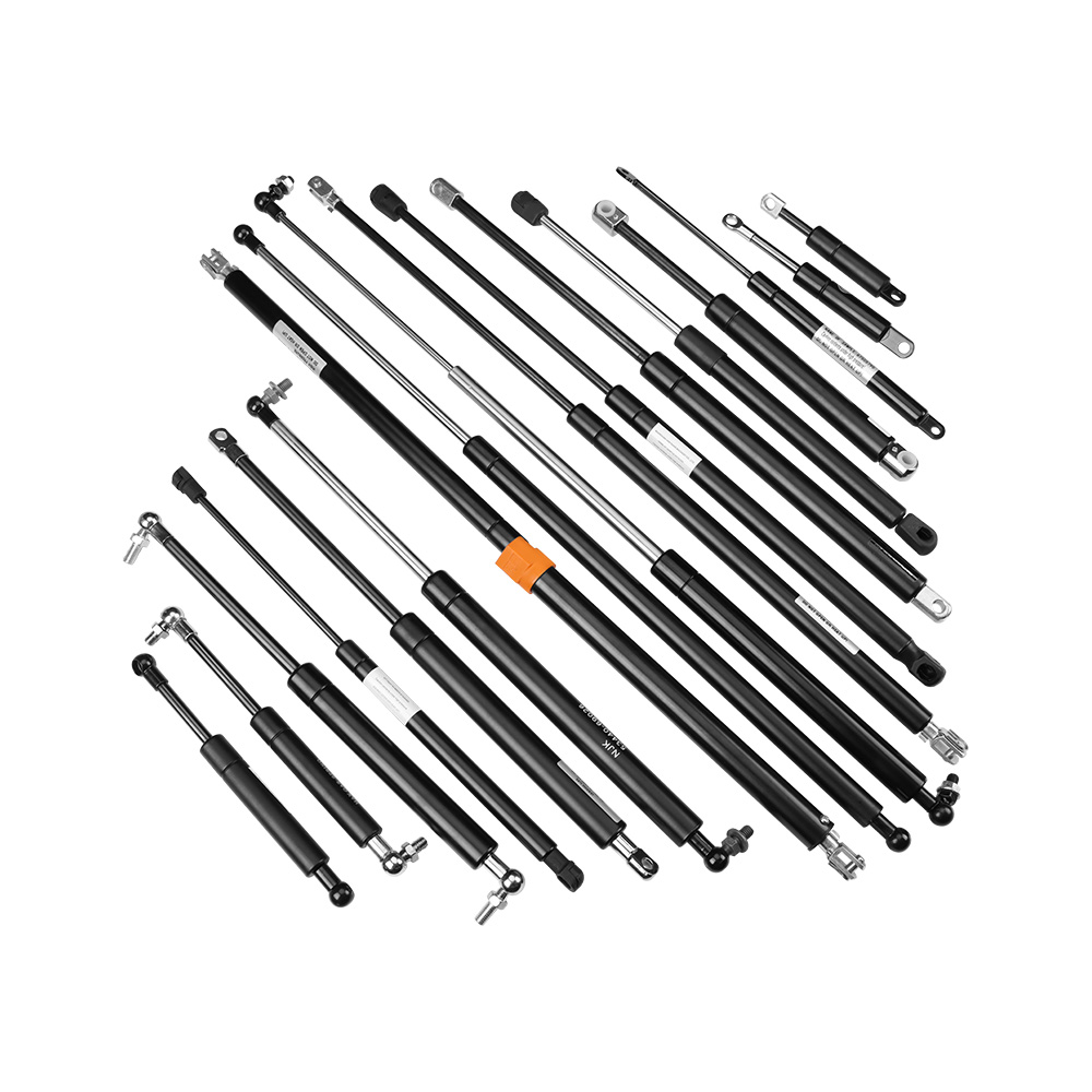
Physical orientation dictates the internal component function of any pressurized lifting cylinder. The way you mount the hardware directly impacts how internal fluids and gases interact with the piston and seals. Understanding these internal mechanics is critical for maximizing lifespan and ensuring predictable motion control.
| Mounting Orientation | Internal Fluid Behavior | Damping Performance | Seal Lubrication |
|---|---|---|---|
| Rod-Down (Recommended) | Oil pools at the seal end. Piston travels through oil at full extension. | Excellent soft-close and controlled stop. | Continuous lubrication prevents seal dry-out. |
| Rod-Up | Oil pools at the tube base. Gas hits the seal directly. | Abrupt stop at full extension; poor damping. | High risk of seal dry-out and gas leakage. |
| Horizontal | Oil distributes along the tube wall. | Inconsistent damping depending on slight angle variations. | Partial lubrication; lower lifespan than rod-down. |
| Variable Angle (Moving) | Fluid shifts dynamically during the stroke. | Requires careful calculation to ensure oil reaches the seal at full extension. | Adequate if the final resting position is rod-down. |
Maximizing damping and soft-close functionality requires specific internal fluid dynamics. A standard hydraulic strut contains pressurized nitrogen gas and a small volume of oil. When mounted in a rod-down orientation, gravity forces the oil to pool at the lowest point, resting directly against the main seal. As the cylinder extends, the piston travels through the nitrogen gas for most of the stroke. Near full extension, the piston enters the oil zone. Forcing the piston through this viscous fluid creates the necessary hydraulic resistance for a soft, controlled stop, preventing the lid from slamming open and damaging the hinges.
Mounting angles that cause rapid compression or extension cycles increase internal stress significantly. Fluid dynamics principles dictate that higher piston velocities scale the resistance force of the internal valving. If the geometry forces the piston to move too quickly, the internal oil cannot pass through the piston orifice fast enough. This creates an exponential spike in resistance, which can bend the rod, blow out the internal seals, or tear the mounting brackets out of the substrate.
Seal degradation remains the primary cause of failure in pressurized lifting mechanisms. Maintaining an optimal downward angle keeps the internal seal lubricated. A dry seal becomes brittle, allowing the pressurized nitrogen gas to escape, rendering the unit useless. Extending the operational lifecycle requires strict adherence to rod-down mounting whenever possible. Certain design scenarios demand horizontal or rod-up mounting due to space constraints. In these specific cases, engineers must specify specialized double-acting or internal-chamber designs that bypass standard orientation rules by utilizing internal floating pistons to manage oil placement.
Mapping physical dimensions to hardware specifications requires a structured evaluation framework. Engineers must translate the weight of the lid, the location of the center of gravity, and the desired opening angle into precise mounting coordinates. Guesswork during this phase leads to erratic performance and compromised safety.
The most reliable starting point for any geometric layout is the 1/3 length rule. This principle dictates locating the moving mounting point approximately one-third the distance from the hinge to the outer edge of the lid. For example, if a heavy access panel measures 900mm from the hinge to the handle, the moving mounting point should sit roughly 300mm away from the hinge. This specific geometry balances stroke length requirements with mechanical leverage. Moving the point closer to the hinge requires exponentially more force to lift the lid, while moving it further away requires an impractically long stroke length.
Force response curves vary drastically between vertical and horizontal mounting configurations. A Gas Strut mounted nearly vertically when closed yields a highly linear force response. The vertical orientation aligns the lifting force directly against gravity, making the initial lift feel effortless. Conversely, horizontal mounting creates exponential force spikes at the extremes of the stroke. When mounted horizontally, the initial force pushes laterally into the hinge rather than vertically against the load. This requires a massive initial exertion from the user to open the panel, followed by a sudden, aggressive upward acceleration once the angle increases.
Retrofitting manual supports to replace motorized or heavy mechanical actuators presents unique geometric challenges. Applications like vehicle camper shells, heavy machinery access panels, or pop-up roofs often feature existing mounting points optimized for active mechanical drives. Transitioning to self-contained nitrogen cylinders requires recalculating these mounting points entirely. Active drives provide constant force regardless of angle, whereas pressurized cylinders rely on moment arms. Fabricators must measure the exact center of gravity and shift the mounting brackets to ensure the new cylinders provide adequate initial lift without over-extending the existing hinge structures.
Selecting the right hardware involves conceptual trade-offs based on finalized angular calculations. Buyers must evaluate overall value-influencing factors, balancing stroke length, force ratings, and adjustability against the physical constraints of their application.
Choosing between fixed and adjustable units often dictates the success of a prototyping phase. Pre-charged fixed units arrive with a specific internal pressure, making them ideal for high-volume production where the geometry is perfectly verified. However, theoretical force calculations frequently differ from real-world friction, hinge resistance, and uneven weight distribution. Utilizing an adjustable gas spring allows engineers to bleed off nitrogen pressure incrementally on the physical prototype. This flexibility mitigates the risk of ordering incorrect fixed-force units for complex angular geometries, saving significant time and prototyping costs.
The chosen mounting angle directly dictates the required stroke length and the extended-to-compressed ratio. A steep mounting angle positioned far from the hinge requires a longer stroke and a longer overall extended length to achieve the desired opening angle. This setup provides excellent mechanical advantage but requires substantial physical space inside the enclosure. A shallow angle positioned close to the hinge requires a much shorter stroke but demands significantly higher internal pressure to overcome the poor mechanical leverage. Engineers must balance these physical space constraints against the maximum force ratings of the available gas spring catalog.
When finalizing specifications, consider the environmental factors that interact with your chosen mounting angle. Extreme temperature fluctuations alter the internal pressure of the nitrogen gas. If your mounting geometry relies on a very narrow margin of force to hold a lid open, a drop in ambient temperature might cause the lid to sag. Building a 10% to 15% force buffer into your calculations ensures the panel remains securely open even in adverse conditions, provided the mounting angle offers sufficient mechanical leverage.
Identifying common failure modes during installation allows fabricators to engineer risks out of the final design. Poor mounting angles manifest as distinct mechanical failures that compromise both the hardware and the surrounding structure.
Hinge binding and excessive pivot friction occur when the support is mounted too close to the hinge or at an angle less than 10° when closed. In this configuration, the force vector directs laterally into the hinge pivot rather than vertically against the load. The cylinder acts as a wedge, trying to rip the hinges off the frame rather than lifting the door. Correcting this requires moving the lower mounting bracket further down the frame to increase the closed angle, redirecting the force upward.
Over-extension and bottoming out represent severe mechanical failures. This occurs when the mounting angle forces the internal piston to act as a physical limit stop for the heavy door. Pressurized cylinders are designed to lift and dampen, not to serve as structural stops. If the door reaches its maximum opening angle and the cylinder bottoms out internally, the leverage of the heavy door will easily rip the ball studs out of their sockets or bend the piston rod. Mitigation strategies include incorporating external mechanical stops, safety lanyards, or adjusting the fixed mounting brackets to ensure the cylinder operates within its designed stroke limits, leaving a few millimeters of unused stroke at full extension.
High-velocity impact stress destroys internal valving rapidly. Incorrect angles that cause the door to fly open unchecked force the piston to move too quickly through its stroke. This high-impact bottoming out leads to immediate seal blowout or structural failure of the mounting brackets. If the geometry cannot be changed to slow the door down, engineers must specify custom internal valving to increase the hydraulic resistance and manage the excessive velocity.
To ensure a successful installation and maximize the lifespan of your lifting mechanisms, follow these immediate next steps:
Measure the exact distance from your hinge pivot to the center of gravity of your lid or panel.
Calculate your moving mounting point using the 1/3 length rule to establish a baseline geometry.
Verify your closed mounting angle with a digital inclinometer to ensure it falls between 10° and 30°.
Select an adjustable unit for your initial prototype to dial in the exact force required before ordering fixed-pressure production units.
Install external mechanical stops to prevent the cylinder from bottoming out at full extension.
A: The optimal installation angle is typically 10° to 30° from the fully closed position. This angle ensures optimal lifting force, prevents lateral hinge binding, and allows for smooth, predictable opening transitions without overloading the pivot hardware.
A: While some specialized double-acting springs permit alternative orientations, a rod-down orientation is critical for standard supports. Mounting rod-down ensures internal seal lubrication and provides predictable end-of-stroke damping as the piston travels through the oil zone.
A: Apply the 1/3 rule by measuring from the hinge to the moving point, setting it at approximately 33% of the lid's total length. Adjust this baseline based on the lid's exact center of gravity and calculate the resultant force vectors to ensure smooth operation.
A: Yes. Incorrect angles can cause lateral side-loading on the piston rod, force excessive velocity through the internal valving, or dry out the main seal by preventing proper oil pooling, significantly reducing the operational lifespan of the unit.
A: Mounting the unit too parallel to the closed lid directs the force vector directly into the hinge pivot rather than upward against the weight of the door. This lateral pressure causes mechanical lock-up and severe structural hinge damage.
A: You can use digital smartphone inclinometer applications or basic geometric formulas measuring the rise and run to quickly verify closed and open angles during installation, ensuring the physical prototype matches your design files.
A: Yes. Adjustable models allow you to bleed off nitrogen pressure incrementally. This helps you find the exact force required to match newly calculated mounting angles without needing to buy multiple fixed-force units during the prototyping phase.


