

close
Choose Your Site
Global
Social Media

Author: Site Editor Publish Time: 2026-07-29 Origin: Site
Standard gas springs deliver a predictable, relatively linear force profile. Real-world application loads, such as heavy machinery covers, access hatches, and ergonomic equipment, often present non-linear, variable, or shifting weight distributions. This fundamental engineering conflict in kinematics creates a significant design challenge. When the force profile fails to match the changing load, engineers face compromised user ergonomics, accelerated hinge wear, and safety hazards from falling loads. It also triggers a costly cycle of repeatedly re-specifying gas struts during prototyping.
Moving from fixed-force constraints to dynamic solutions requires a strategic approach. Engineers achieve precise load-matching through specific hardware choices. You can optimize kinematics using an Adjustable Gas Spring, variable mounting geometries, and specialized internal valving. This guide explains how to calculate, select, and implement the right pneumatic hardware to handle shifting application loads safely and efficiently.
Prototyping Efficiency: Adjustable gas struts equipped with bleed valves allow engineers to empirically dial in the exact force required in situ, eliminating theoretical calculation errors before mass production.
Positional Control: When loads change dynamically during operation, integrating a locking gas spring provides absolute positional stability regardless of weight shifts.
Kinematic Optimization: Force matching is not solely about internal pressure; altering the moment arm and mounting geometry is equally critical to managing changing load curves.
Application Specificity: Selecting between a controllable gas spring (for damping/speed control) and a lockable gas spring (for rigid holding) dictates the safety and usability of the final product.
Understanding how a gas spring interacts with a moving load requires analyzing the underlying pressure mechanics. The output force equals the internal pressure minus the external atmospheric pressure, multiplied by the cross-sectional area of the rod. While this formula defines the baseline force, the actual load exerted on the spring changes constantly during operation. You must account for these variations to prevent system failure.
As a lid, hatch, or monitor arm moves through its arc, the center of gravity shifts. This shift changes the effective weight the spring must support at different angles. The load curve discrepancy occurs because the spring's linear force output rarely aligns perfectly with the non-linear gravitational pull of the shifting center of gravity. When designing a lifting mechanism, you have to map this curve accurately.
To properly evaluate the shifting center of gravity, follow these steps:
Identify the total weight of the moving component, including all attached hardware and accessories.
Determine the exact center of gravity coordinates in both the closed and fully open positions.
Calculate the horizontal distance from the pivot point to the center of gravity at various angles of opening.
Plot the required lifting force at 10-degree increments to visualize the load curve.
Compare the required force curve against the theoretical output curve of the selected gas strut.
In a typical four-bar linkage system, you must analyze the load distribution starting from the side where the load is applied. The force transfers through the structure to where it impacts the gas spring via the upper member. The relationship between the torque exerted by the payload weight and the counter-torque provided by the gas spring fluctuates across the entire range of motion. Mapping this torque curve is essential to prevent dead zones where the hatch might stall or slam shut.
Consider a heavy industrial access panel. When fully closed, the center of gravity is furthest from the hinge horizontally, creating maximum torque. As the panel opens and approaches a vertical position, the horizontal distance decreases, reducing the torque. If the gas spring force remains too high near the fully open position, it will forcefully snap the panel open, potentially damaging the hinges or injuring the operator.
Several external factors can drastically alter the effective load on your pneumatic system. You must anticipate these variables during the design phase to ensure long-term reliability.
Added Mass: End-user modifications drastically change the baseline weight. Adding heavy monitors to a desk or mounting thick insulation on a machine cover requires immediate force compensation.
Environmental Factors: Temperature fluctuations alter internal nitrogen gas pressure. You can expect approximately a 3.4% force change per 10°C change. This alters the spring's output force even if the physical payload remains constant.
Mechanical Degradation: Over time, friction increases in hinges, joints, and pivots. This degradation requires higher breakaway forces to initiate movement, effectively acting as an increased load.
Wind Loading: For outdoor applications like vehicle hatches or exterior enclosures, wind gusts can apply sudden, unpredictable forces that the gas strut must resist.
| Temperature (°C) | Internal Pressure Change | Effective Force Output |
|---|---|---|
| -10 | -10.2% | Significantly Reduced |
| 20 (Baseline) | 0% | Nominal |
| 50 | +10.2% | Significantly Increased |
| 80 | +20.4% | Maximum Safe Limit |
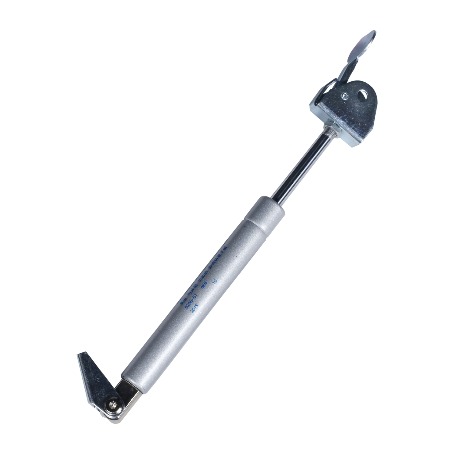
When standard fixed-force units fail to accommodate shifting weights, engineers rely on specialized pneumatic hardware to bridge the gap. Selecting the correct type of strut is the foundation of a successful kinematic design.
These units ship at maximum internal pressure and feature an integrated release valve, typically a grub screw or push-pin. This mechanism allows designers to install the spring, load the application, and incrementally vent nitrogen gas until perfect equilibrium is achieved. It serves as a highly effective prototyping tool. However, this is a one-way adjustment. You can only decrease the force; increasing it requires factory re-pressurization.
The bleeding process requires patience and precision. You install the strut, test the movement, and if the force is too high, you briefly depress the valve. You release a tiny amount of gas, re-test the movement, and repeat until the panel opens smoothly and stays open without excessive force. This empirical method accounts for all the minor friction and weight variations that theoretical calculations often miss.
A locking gas spring features an internal piston valve controlled by an external release pin. When the pin is depressed, the rod moves freely. When released, the valve closes, locking the rod in place. Rigid locking utilizes an oil chamber for zero compression or extension under heavy changing loads. Elastic locking uses a gas chamber to provide slight shock absorption. These mechanisms are vital in variable-load systems requiring intermediate holding positions.
Consider a medical bed or a specialized ergonomic chair. The load changes constantly as the patient shifts their weight. A standard strut would compress or extend unpredictably. The locking mechanism ensures the backrest or leg rest remains exactly where the operator sets it, providing absolute stability regardless of how the load shifts.
A controllable gas spring utilizes advanced metering techniques to govern the rate of extension and compression. Manufacturers utilize internal metering orifices, varying fluid viscosity, and dynamic damping via oil bypass grooves. These technologies prevent aggressive snap-back when a load is suddenly removed, ensuring smooth, controlled motion regardless of weight fluctuations.
Damping is particularly important at the end of the stroke. As a heavy hatch reaches its fully open position, the required lifting force drops significantly. Without damping, the excess force from the gas strut would slam the hatch into its mechanical stops. Internal oil zones slow the piston down in the final few millimeters of travel, providing a soft, controlled stop.
Force matching relies on two primary levers: altering the physical geometry of the linkage or changing the pneumatic hardware specifications. Often, a combination of both yields the best results.
Moving the mounting points changes the mechanical advantage of the system. There is an inverse relationship between stroke length and hinge force. Using a longer gas spring over a larger moment arm reduces the stress on hinges and mounting brackets when loads increase. This geometric adjustment often solves load issues without requiring higher-pressure springs.
If you move the lower mounting point further away from the hinge, you increase the moment arm. This means the gas strut has more leverage over the load. Consequently, you can use a strut with a lower internal pressure to lift the same weight. This reduces the reaction forces acting on the hinges, extending the lifespan of the entire assembly.
Engineers utilize gas spring force calculators to model dynamic loads accurately. Precise calculations require specific input variables: total lid weight, hand force limits, hinge position, stroke length, and center of gravity coordinates. Reviewing interactive sizing diagrams helps determine optimal rod and cylinder diameters before finalizing hardware selection.
Input the exact weight of the moving panel into the modeling software.
Define the X and Y coordinates of the center of gravity relative to the main pivot point.
Specify the desired starting and ending angles of the movement.
Input the maximum allowable hand force for the operator.
Run the simulation to generate a list of viable mounting coordinates and required strut pressures.
Select the configuration that minimizes hinge stress while maintaining smooth operation.
Using a bleed-valve spring offers immense flexibility for one-off custom builds. For OEM production, it serves purely as a prototyping tool to determine fixed-force specs. Once the ideal pressure is found via venting, engineers order fixed-force production units matching that exact specification to reduce costs and eliminate tampering risks.
| Hardware Type | Primary Function | Best Use Case |
|---|---|---|
| Adjustable Bleed Valve | One-way force reduction | Prototyping, custom low-volume builds |
| Locking (Rigid/Elastic) | Absolute positional holding | Medical beds, seating, dynamic shifting loads |
| Controllable/Damped | Velocity and speed control | Heavy safety covers, automated hatches |
| Fixed Force Standard | Consistent linear output | High-volume OEM production with known loads |
Ergonomic furniture requires frequent adjustments. Specifying an adjustable desk gas spring allows the end-user to easily manage loads ranging from lightweight laptops to heavy multi-monitor setups. The internal valving must handle these rapid weight changes without failing or requiring manual recalibration by the user.
Conversely, heavy industrial covers mandate a lockable gas spring for OSHA compliance. This ensures operator safety by preventing accidental closure if the load shifts unexpectedly. In these environments, the locking mechanism must be robust enough to withstand significant shear forces and vibration without slipping.
Implementing dynamic load solutions introduces specific engineering risks that require careful mitigation. You cannot simply swap components without analyzing the systemic impact.
Compensating for a heavier load by simply increasing gas pressure can exceed the shear strength of the hinges or the mounting brackets. To mitigate this risk, recalculate the linkage geometry. Distribute the load across a wider moment arm rather than just brute-forcing the pressure through a short pivot point. High pressure in a confined geometry acts like a pry bar against your hinges.
Adjustable valves, metering orifices, and locking pins introduce additional potential leak paths for nitrogen gas. Specify high-grade nitrile or Viton seals based on the operating environment. Always ensure the rod is mounted rod-down. This orientation keeps the internal oil resting on the seals, maintaining lubrication and preventing premature gas leakage.
Accidental over-venting renders the unit unusable for the specific load. Establish strict, incremental venting protocols during the calibration phase. Vent the gas in half-second bursts, testing the load balance after each release to prevent dropping the pressure below the required threshold. Wear safety glasses and hearing protection during this process, as the escaping nitrogen is under high pressure.
Matching a changing load requires a dual approach: optimizing the kinematic geometry and selecting the correct pneumatic hardware. Choose a standard adjustable unit for prototyping and static load calibration. Opt for locking mechanisms when the load changes dynamically during use and requires absolute positional holding. Select controllable damping when the speed of movement under varying loads is the primary safety concern.
Utilize online force calculators to establish baseline geometry and moment arms before ordering parts.
Order adjustable prototypes at maximum estimated pressure to allow for empirical field calibration.
Conduct physical load testing across the entire temperature operating range before locking in OEM specifications.
Verify hinge shear strength limits against the calculated maximum reaction forces.
Document the exact venting procedure and final pressure settings for future production runs.
A: Yes, adjustable gas struts feature a bleed valve that allows users to release nitrogen gas, incrementally lowering the force to match the specific load capacity. They cannot be manually re-pressurized.
A: Force is calculated by determining the weight of the load, the center of gravity, and the distance from the hinge to the gas spring mounting point, using the formula F = (W × D) / (n × d), adjusted for link geometry.
A: A standard gas spring provides continuous push or pull force over its stroke. A lockable gas spring contains an internal valve that, when closed, rigidly holds the rod at any point along its stroke, regardless of load changes.
A: Yes. Increasing the internal pressure of the spring directly increases the reaction force on the hinges. To mitigate this, engineers should choose a longer gas spring to increase the moment arm.
A: Gas spring force changes by approximately 3.4% for every 10°C change in temperature due to gas expansion or contraction, which must be factored into the initial load calculations.
A: It is a gas spring designed with specific internal metering or damping to strictly control the velocity of the stroke, preventing damage when loads suddenly shift.


