

close
Choose Your Site
Global
Social Media

Author: Site Editor Publish Time: 2026-07-30 Origin: Site
Modern ergonomic seating demands precise, reliable adjustability. Moving beyond basic pneumatic lifts, advanced locking systems are now standard requirements for medical, industrial, and high-end ergonomic chairs. Incorrect specification and integration of a locking chair adjustment gas spring leads to frame stress, premature seal failure, actuation linkage binding, and ultimately, user instability and warranty claims. Successfully integrating these components requires a rigorous evaluation of locking mechanisms, load calculations, and actuation geometry. This guide breaks down the technical criteria for selecting and implementing the correct controllable gas spring for specialized seating applications.
Locking Type Dictates Application: Specify rigid vs. elastic (flexible) locking based strictly on the application's tolerance for vertical deflection (e.g., medical chairs require rigid compression locking; standard office chairs utilize elastic locking).
Actuation Geometry is Critical: The design of the actuation linkage (lever vs. Bowden cable) directly impacts the lifespan of the push pin mechanism and determines the user's perceived quality of the chair.
Mitigate Lateral Loading: Proper mounting orientation and the use of external support tubes are mandatory to prevent side-loading, which is the primary cause of premature gas leakage and seal degradation.
Compliance Requires Dynamic Testing: Meeting industry standards (such as ANSI/BIFMA) requires evaluating the gas spring under dynamic drop loads, not just static weight capacities.
The operational core of any controllable cylinder is the release pin located at the rod end. This small mechanical interface dictates the entire behavior of the cylinder. When stationary, internal pressure forces the valve shut, isolating the internal chambers. The moment mechanical force is applied to depress this pin, the internal valve opens. This state-change transition allows the unit to behave exactly like a standard compression cylinder, permitting the piston rod to travel freely through the tube. You must ensure the linkage engaging this pin operates smoothly without binding.
Understanding the internal fluid dynamics is essential for proper frame integration. Depressing the pin opens the piston valve, allowing pressurized nitrogen gas and damping oil to flow between the chambers separated by the piston. This flow facilitates stroke movement. As soon as the actuation force is removed, the pin returns to its resting state, the valve closes instantly, and the fluid flow is blocked. This isolates the chambers and locks the piston rod securely in its current position. Field failures often occur when dirt or debris prevents this pin from fully resetting.
The standard actuation force required to depress the pin depends heavily on the internal cylinder pressure. Higher extension forces inherently require more mechanical force to open the valve. Engineers must account for this when designing the release lever, ensuring the mechanical advantage of the handle overcomes the internal pressure without requiring excessive effort from the seated user. If the lever ratio is wrong, users will struggle to adjust the seat height, leading to complaints and perceived poor quality.
We often see prototypes fail because the design team underestimated the internal pressure ramp-up. When the cylinder is fully compressed, the internal pressure is at its peak. The release mechanism must be robust enough to handle this peak pressure without bending or deflecting. Using hardened steel for the actuation lever and ensuring a direct, unhindered path to the push pin are practical steps to avoid this issue.
Elastic locking, often referred to as flexible locking, relies on gas-backed chambers. When the valve closes, the piston is held in place by compressed nitrogen. Because gas is compressible, this setup allows for a slight cushioning or bounce when locked under load. This elastic behavior is the standard for a basic desk gas spring and ergonomic office seating, where user comfort and shock absorption take precedence over absolute positional rigidity. It absorbs the initial shock when a user sits down, protecting both the user's spine and the chair's frame.
Rigid locking in compression utilizes an oil-chamber locking mechanism. Oil, unlike gas, is incompressible. When the valve closes, the piston rests against a solid column of oil, preventing any downward movement under load. It secures the piston rod firmly in the compression direction, resisting force to eliminate vertical play. This is a strict safety and precision requirement for medical chairs, drafting stools, and heavy-duty industrial seating where unprompted deflection could cause injury or disrupt sensitive work. If a surgeon is operating, their stool cannot sink even a millimeter.
Rigid locking in extension prevents upward movement when the cylinder is locked. While less common for primary seat height adjustment, this mechanism is frequently utilized in specific tilt, backrest, or recline mechanisms. It ensures that a backrest remains firmly in its designated angle without springing forward when the user shifts their weight. Combining these locking types allows for highly customized seating solutions tailored to specific operational environments.
To clarify the differences, review the following comparison of locking mechanisms used in seating applications:
| Locking Type | Primary Medium | Behavior Under Load | Typical Application |
|---|---|---|---|
| Elastic (Flexible) | Nitrogen Gas | Slight bounce/cushioning | Standard office chairs, task seating |
| Rigid in Compression | Hydraulic Oil | Zero downward deflection | Medical stools, industrial workstations |
| Rigid in Extension | Hydraulic Oil | Zero upward deflection | Backrest tilt, heavy-duty recliners |
Calculating the required extension force is the first step in cylinder specification. The formula must account for the total seat weight, target user percentiles, and the specific leverage ratios of the chair frame. If the force is too low, the chair will not rise when the user actuates the lever; if it is too high, lighter users will be unable to lower the seat. You must test these calculations with physical prototypes loaded with actual weights to verify real-world performance.
Force progression refers to the natural increase in resistance as the spring is compressed. Because the piston rod displaces internal volume as it enters the tube, internal pressure rises. Managing this progression is critical for user experience. A steep progression curve means the user will have to exert significantly more effort to reach the lowest seat height, negatively impacting the ability to lower the chair smoothly. Selecting a cylinder with a larger outer tube volume can help flatten this progression curve.
Determining the optimal stroke length requires mapping the required height range against the physical constraints of the base and seat pan. The methodology involves calculating the maximum extended height and the minimum compressed height, ensuring the cylinder provides the necessary travel without bottoming out internally or causing the chair base to drag on the floor. The physics-based user expectation is clear: the system must hold the occupant securely in its locked position, yet allow smooth downward movement upon manual actuation under load.
Follow these steps to determine the correct stroke length for your seating frame:
Measure the distance from the floor to the top of the star base hub.
Determine the required minimum and maximum seat pan heights based on ergonomic standards.
Calculate the available vertical space between the base hub and the under-seat mechanism at the lowest position.
Select a stroke length that fits within this available space while providing the necessary vertical travel.
Verify that the extended cylinder does not exceed the maximum allowable seat height.
The chair's center of gravity drastically impacts the vertical alignment and longevity of the cylinder. If the seat pan design shifts the user's weight too far forward or backward, it introduces a bending moment on the piston rod. Frame geometry must align the central axis of the cylinder as closely as possible with the anticipated center of mass to ensure pure axial loading. Misalignment leads to uneven seal wear and premature failure.
External support tubes, often called standpipes, serve a dual purpose in seating design. First, they function as a structural sleeve that absorbs lateral forces, effectively eliminating side-loading on the fragile internal seals of the cylinder. Second, they act as the primary physical and mechanical lock interface, securing the entire assembly within the star base and the under-seat mechanism through standardized tapers. A loose fit here will cause the entire chair to wobble.
Mounting orientation is dictated by internal lubrication requirements and the specific locking type. Most seating cylinders are designed to be mounted rod-down. This orientation ensures that the internal damping oil rests against the main seal, keeping it lubricated and preventing the nitrogen gas from escaping. Proper orientation preserves seal integrity and ensures the locking mechanism engages instantly without a spongy feel. Never mount a standard rod-down cylinder upside down, as it will dry out the seal and fail rapidly.
When comparing a standard office chair gas lift against a fully controllable unit, the primary differentiator is positional authority. Standard lifts offer basic elastic locking suitable for general office tasks. In contrast, multi-position rigid locking cylinders provide absolute stability. Standard industrial units are frequently structurally modified with these advanced locking functions to ensure the safety, stability, and positioning flexibility required for specialized medical and technical seating.
Specifying rigid locking mechanisms for non-critical commercial office applications often presents a poor cost-to-benefit ratio. The incompressible oil chambers and tighter manufacturing tolerances increase unit costs. For a standard workstation, elastic locking provides adequate support and superior comfort. However, in surgical or precision manufacturing environments, the higher cost of rigid locking is a necessary investment in safety and operational accuracy. You do not want to over-engineer a basic task chair and destroy your profit margins.
Cylinder diameter also plays a role in base compatibility and aesthetics. Standard 50mm outer tubes fit the vast majority of commercial star bases. Upgrading to heavy-duty 65mm or larger diameters for bariatric or intensive-use seating requires corresponding changes to the base hub and under-seat mechanism, impacting both the visual profile and the overall weight of the chair. Ensure your base supplier can accommodate the larger taper dimensions before committing to a heavy-duty cylinder.
Standardizing taper dimensions across different chair models is a fundamental strategy for streamlining procurement and base manufacturing. Utilizing universal Morse tapers ensures that cylinders from multiple vendors will seat correctly into the same base and mechanism designs, preventing assembly line bottlenecks. If you use proprietary tapers, you lock yourself into a single supplier and risk production halts if they experience delays.
Manufacturers must evaluate the trade-offs between ordering custom stroke lengths and utilizing off-the-shelf dimensions. Custom strokes allow for perfectly tailored seat heights but introduce longer lead times and minimum order quantities. Off-the-shelf dimensions enhance supply chain resilience and reduce costs, though they may require minor compromises in the final ergonomic height range of the chair. Always design your frames to accept standard lengths whenever possible.
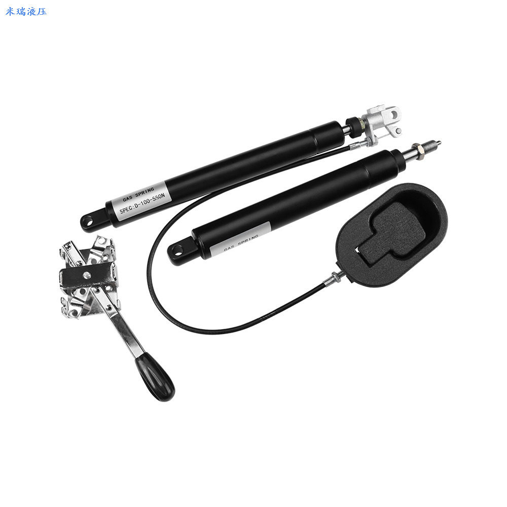
Direct lever systems are the industry standard for under-seat mounting. They offer mechanical simplicity, exceptionally low failure rates, and direct tactile feedback. Because the lever physically presses against the release pin without intermediate components, there is minimal risk of stretching or routing interference. Keep the lever design simple and robust to ensure decades of reliable use.
Bowden cable release systems are specified for remote actuation in complex, multi-axis adjustable chairs. When controls must be mounted on armrests or integrated into a centralized control pod, cables provide the necessary routing flexibility. However, these systems introduce friction and routing challenges. Tight bends in the cable path can cause the inner wire to bind, leading to delayed valve closure or a failure to lock completely. Route cables with wide, sweeping curves to minimize internal friction.
Ergonomic limits dictate that a user should not have to exert excessive force to adjust their chair. Engineers must calculate the required push pin actuation force and build sufficient mechanical advantage into the release lever. A standard lever ratio is typically required to ensure smooth operation across all user demographics. Test the actuation force with a force gauge to ensure it falls within acceptable ergonomic limits.
Designing linkages that minimize dead travel is critical for a premium feel. However, tolerances must strictly prevent continuous, partial engagement of the push pin. If a poorly adjusted cable or a heavy lever rests on the pin, it can hold the internal valve slightly open. This causes slow pressure leaks, unintended drifting of the seat height, and eventual failure of the locking mechanism. Always build in a small amount of intentional slack to guarantee the valve closes fully.
Lateral forces, or side-loading, represent the primary failure mode for pneumatic cylinders. When a piston rod is subjected to bending forces, it presses unevenly against the main seal, causing rapid wear and allowing nitrogen to escape. Designing tight frame tolerances and utilizing rigid support tubes are the most effective methods to eliminate non-axial loads and preserve internal pressure. Do not rely on the cylinder itself to provide structural rigidity to the chair frame.
Environmental factors heavily influence component lifespan. In industrial, manufacturing, or medical environments, debris, dust, and aggressive cleaning chemicals can degrade the exposed piston rod and main seal. Integrating protective bellows, dust covers, or specialized wiper seals prevents particulate matter from entering the cylinder housing, ensuring long-term reliability. A simple plastic dust cover can extend the life of a cylinder by years in a harsh environment.
Integrating ANSI/BIFMA X5.1 testing requirements into the seating prototype phase is non-negotiable for commercial viability. These standards dictate rigorous performance baselines that the entire chair assembly, including the height adjustment mechanism, must survive. Failing these tests means your product cannot be sold into major corporate or government contracts.
Compliance requires specific dynamic evaluations. Drop testing simulates a heavy user falling into the seat, testing the cylinder's ability to absorb shock without catastrophic failure. Cyclic durability testing of the locking mechanism ensures the valve can open and close hundreds of thousands of times without leaking. Furthermore, extreme temperature testing is necessary to verify that oil viscosity and gas pressure remain stable, ensuring the chair functions correctly regardless of the operating environment. Build a dedicated test rig in your facility to run these cycles continuously.
Utilize adjustable-force prototypes equipped with release valves to dial in the exact extension force required before finalizing production specifications.
Audit the actuation linkage design to ensure zero resting pressure on the push pin to prevent drifting and slow leaks.
Implement strict tolerance checks on support tubes to eliminate side-loading during final assembly.
Conduct in-house dynamic drop testing prior to submitting the final chair design for official certification.
A: A standard lift uses gas-backed elastic locking, allowing a slight bounce for comfort. A compression-locking spring uses an incompressible oil chamber, providing absolute rigidity and preventing any downward movement under load, which is essential for medical and industrial seating.
A: The most common causes are seal degradation from lateral side-loading, debris damaging the piston rod, or an improperly adjusted actuation lever that constantly applies slight pressure to the release pin, keeping the internal valve partially open.
A: No. Most seating cylinders must be mounted rod-down. This ensures the internal damping oil rests against the main seal, keeping it lubricated to prevent gas leakage and ensuring the locking mechanism engages properly.
A: Flexible locking uses compressed gas, allowing the seat to cushion the user's weight. Rigid locking uses oil to eliminate all vertical play, locking the seat solidly in place without any bounce.
A: Stroke length is calculated by taking the required maximum extended seat height and subtracting the minimum compressed height, while accounting for the physical dimensions of the star base and under-seat mechanism to prevent bottoming out.
A: This is typically caused by friction in a Bowden cable routing, a bent release pin from excessive force, or a lack of mechanical advantage in the lever design that prevents it from fully returning to its neutral, closed-valve position.


