

close
Choose Your Site
Global
Social Media

Author: Site Editor Publish Time: 2026-07-31 Origin: Site
Controlled motion is a non-negotiable element of modern automotive design, directly impacting user safety, ergonomic comfort, and the perceived build quality of the vehicle. When a driver opens a trunk or lifts a hood, the expectation is a smooth, effortless, and secure movement. Premature failure of lifting mechanisms, sluggish operation in extreme temperatures, or aggressive end-of-stroke impacts lead to safety hazards, negative user experiences, and costly warranty claims. A failing strut can cause a heavy hood to unexpectedly drop or a tailgate to slam shut, posing severe risks to operators and mechanics alike. Addressing these issues requires precision engineering from the outset. Selecting the correct automotive gas spring requires moving beyond basic dimensions to evaluate hydro-pneumatic mechanics, damping profiles, load capacities, and environmental resilience. This guide provides a technical framework for specifying gas struts that ensure reliable vehicle motion.
Application-Specific Damping: Matching the damping characteristics (hydraulic vs. dynamic) to the specific vehicle component prevents structural damage at the end of the stroke.
Orientation Dictates Lifespan: Proper mounting orientation (typically rod-down) is critical for maintaining seal lubrication and preventing premature nitrogen gas leakage.
Temperature Resilience: Operating temperature ranges and internal seal quality are the primary differentiators between standard aftermarket replacements and OEM-grade automotive gas springs.
Precision Load Calculation: Accurate force specification prevents both heavy, sluggish operation and overly aggressive extension that stresses mounting points.
An auto gas spring operates as a hydro-pneumatic device, storing potential energy by compressing nitrogen gas inside a sealed cylinder. When the piston rod is pushed into the cylinder, the internal volume decreases, compressing the gas and generating a reactive extension force. A small orifice in the piston allows the gas to flow between the chambers, ensuring smooth, consistent force delivery throughout the stroke. Field mechanics know that consistent pressure retention is what separates a reliable lift from a dangerous drop.
Baseline success criteria for these components include smooth extension, controlled compression, and the ability to lift, lower, and securely position heavy vehicle components at intermediate angles. The internal pressure dictates the lifting capacity, while the precision of the piston and seal assembly determines the operational smoothness. High-quality manufacturing ensures that the nitrogen gas remains contained, providing reliable lifting force over thousands of cycles. We look for specific performance markers during assembly line testing to verify these criteria.
Verify the initial breakaway force required to start compression.
Measure the extension speed across the full stroke length.
Confirm the holding force at the fully extended position.
Test the end-of-stroke deceleration to ensure soft stopping.
Damping prevents aggressive movements that damage vehicle structures. Hydraulic damping relies on a small volume of oil inside the cylinder. As the piston nears the end of its extension stroke, it passes through this oil, slowing the movement. This type of damping is position-dependent, meaning the strut must be mounted in a specific orientation (usually rod-down) to function correctly. If mounted upside down, the piston hits the gas instead of the oil, resulting in a harsh mechanical stop.
Dynamic damping utilizes a longitudinal groove in the inner cylinder wall to control the flow of gas past the piston. This method is position-independent, allowing for more flexible mounting orientations. Proper damping and end-of-stroke dead stops prevent physical damage to the strut assembly, hinges, and vehicle panels by absorbing kinetic energy rather than slamming against structural limits. This controlled deceleration is vital for user safety and component longevity.
| Damping Type | Mechanism | Mounting Requirement | Primary Advantage |
|---|---|---|---|
| Hydraulic | Oil volume at stroke end | Strictly Rod-Down | Proven, cost-effective deceleration |
| Dynamic | Internal cylinder grooves | Flexible / Any Orientation | Consistent damping regardless of angle |
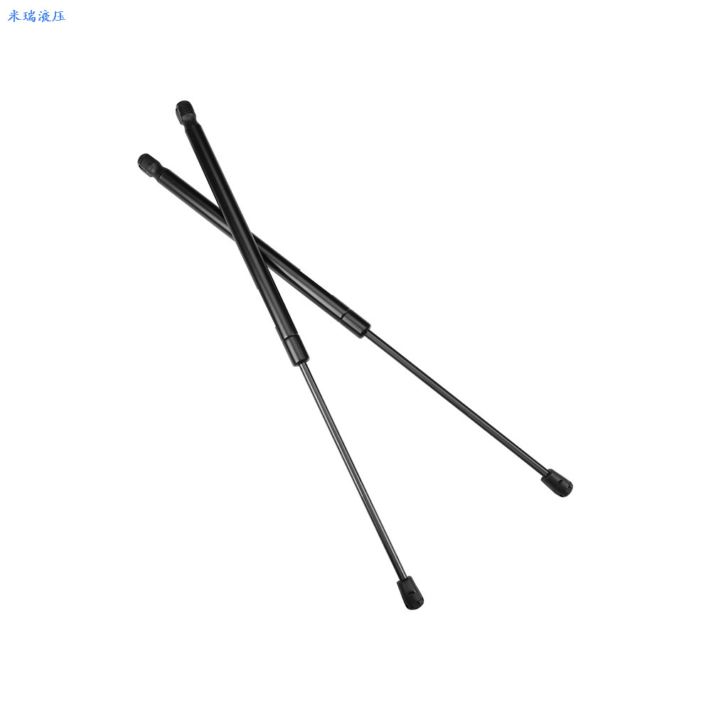
A hood gas strut faces unique environmental challenges, primarily high heat resistance requirements due to its constant proximity to the engine bay. The internal seals and lubrication must withstand elevated temperatures without degrading or losing pressure. Standard struts fail rapidly in this environment, necessitating specialized high-temperature seals made from advanced elastomers. You cannot use a standard trunk strut under the hood; the heat will bake the seals and cause rapid gas loss.
Force requirements and progression curves vary significantly depending on the hood material. Lifting a heavy steel hood requires a different force profile than a lightweight aluminum or composite alternative. Engineers optimize safety features to prevent accidental hood closure under high wind or vibration loads, ensuring the strut holds the hood securely open while a mechanic is working underneath. The progression curve must be steep enough to hold the weight but gentle enough to allow manual closing without excessive effort.
The demands placed on a tailgate gas spring involve high cycle frequency and strict user ergonomic expectations. Rear vehicle access is used daily, requiring a strut that provides effortless lifting and controlled closing over years of operation. The force must be calibrated so the user does not have to struggle to pull the tailgate down, yet it must lift the gate smoothly once unlatched. We calculate the exact pivot geometry to ensure the lift feels weightless to the end user.
Integration challenges arise with automatic or power liftgate systems. These applications require precise synchronization between manual gas springs and motorized actuators. A car trunk gas strut in a powered system often serves to counterbalance the weight, reducing the load on the electric motor and ensuring smooth operation even if the power system fails. The mechanical strut acts as a fail-safe, preventing the heavy liftgate from crashing down if the motor loses power.
Convertible vehicles require specialized gas springs for raising and lowering soft tops and cover panels safely and smoothly. These applications demand precise control to avoid damaging delicate fabric or complex folding mechanisms. The struts must operate flawlessly in both manual and automatic modes, providing consistent support throughout the entire range of motion. A sudden drop or jerky movement can snap a convertible frame linkage instantly.
Space-constrained mounting requirements are common in these specialized applications. Engineers select compact designs that fit within tight clearances while still delivering the necessary force. Hitch-free, reliable operation is critical, as any binding or uneven force delivery can cause the convertible top mechanism to jam or misalign. We often use micro-struts with high internal pressure to meet these tight packaging constraints.
Calculating the required Newton force involves evaluating the component's weight, center of gravity, and the distance to the pivot point. A simple formula balances the torque generated by the heavy panel against the torque provided by the gas spring. Accurate calculations prevent specifying a strut that is either too weak to lift the panel or too strong, making it difficult to close. You have to measure the exact distance from the hinge to the center of gravity to get this right.
The force progression curve illustrates how the pressure changes from the fully extended state (F1) to the fully compressed state (F4). Because the internal volume decreases as the rod enters the cylinder, the force naturally increases. Understanding this progression is vital for ensuring the user experiences a consistent, manageable resistance when closing a hood or trunk. A flat progression curve means the effort feels the same throughout the stroke, which is usually the ergonomic goal.
F1: Force at full extension (holding force).
F2: Force just before full extension during opening.
F3: Force just after initial compression begins.
F4: Force at full compression (maximum resistance).
Cylinder and piston rod materials must be evaluated for corrosion resistance, given their exposure to exterior automotive environments. Nitride-coated steel and stainless steel are common choices, providing durable surfaces that resist rust and wear. A damaged piston rod surface will quickly destroy the internal seal, leading to gas leakage and failure. Even a microscopic scratch on the rod can act like a file against the rubber seal.
Seal integrity requirements are stringent, as components must withstand extreme temperature ranges. Typical specifications require operation from -30°C to +80°C, with engine compartment applications demanding even higher heat tolerance. High-quality seals maintain their elasticity across these extremes, ensuring the nitrogen gas remains securely contained. We specify multi-lip seals for applications exposed to heavy dust and moisture.
Rod-down mounting recommendations are standard for hydraulic-damped gas springs. This orientation ensures that the internal oil rests against the main seal, keeping it lubricated and preventing the nitrogen gas from escaping. Furthermore, the oil provides the necessary end-of-stroke damping as the piston passes through it just before full extension. Mounting a hydraulic strut rod-up is a guaranteed way to cut its lifespan in half.
Physical mounting coordinates and installation angles relative to the hinge pivot alter the effective force, stroke length ratios, and overall stability of the system. Moving the mounting point closer to the hinge requires a stronger spring but allows for a shorter stroke. Engineers optimize these geometries to achieve the desired opening angle and ergonomic feel. The angle of attack changes the mechanical advantage, so precise bracket placement is mandatory.
The trade-off between the lower initial cost of aftermarket struts versus the guaranteed cycle life of OEM-grade components is a major consideration. OEM struts undergo strict quality control and are designed to meet specific warranty compliance standards. While aftermarket options may look identical, they often utilize inferior seals and generic force calibrations that degrade quickly. You get what you pay for when it comes to internal seal quality.
Custom force calibration provided by top-tier manufacturers adds significant value over off-the-shelf standard pressures. A precisely calibrated strut ensures the vehicle panel operates exactly as intended by the design team. Generic replacements often result in a trunk that pops open too aggressively or a hood that sags under its own weight. We always recommend matching the exact Newton rating of the original factory part.
Adjustable gas springs, equipped with release valves to vent nitrogen, are invaluable during the prototyping and testing phases. They allow engineers to physically test different force levels on a physical prototype to find the optimal lifting force without ordering multiple custom samples. Once the ideal pressure is determined, the specifications are locked in. This saves weeks of trial and error during the design phase.
The transition to fixed-force springs for mass production ensures consistency across all manufactured vehicles. Fixed-force units prevent tampering, reduce unit costs, and eliminate the risk of accidental pressure loss through a release valve. This transition is a standard step in moving from vehicle design to assembly line production. You never put an adjustable strut into a final production vehicle.
Lateral loading and side forces applied to the piston rod during operation lead to rapid seal degradation and gas loss. Gas springs are designed to handle axial loads; any bending force will cause the rod to press unevenly against the seal, creating a leak path. This is a common cause of premature failure in poorly designed linkages. If the mounting brackets are misaligned by even a few degrees, the strut will bind.
Mitigation involves specifying appropriate end fittings, such as ball joints or clevis eyes, which allow for slight angular movement. Ensuring precise alignment during installation and designing mounting brackets that absorb lateral movement protects the strut. Proper geometry ensures the force remains strictly linear throughout the entire stroke. We use ball studs almost exclusively to allow for minor chassis flex without side-loading the rod.
The physical properties of compressed gas mean struts become sluggish in freezing winter temperatures and overly aggressive in summer heat. As temperature drops, the gas pressure decreases, reducing the lifting force. Conversely, high heat increases the pressure, making the panel harder to close and faster to open. A trunk that works perfectly in a heated garage might fail to stay open in a snowy driveway.
Mitigating these fluctuations requires specifying multi-chamber designs or temperature-compensating valves for extreme environments. In standard applications, engineers adjust the baseline force calculation to account for the target geographic climate, ensuring the strut maintains adequate lifting capacity in the cold without becoming dangerously forceful in the heat. We calculate a 3% force change for every 10 degrees Celsius of temperature shift.
Excessive kinetic energy during rapid extension causes damage to vehicle mounting brackets, hinges, or the gas spring structure itself. If a heavy tailgate flies open unchecked, the sudden stop at full extension places immense stress on the pivot points. Over time, this stress causes structural fatigue and failure. I have seen hinges completely tear out of sheet metal due to under-damped struts.
Implementing specialized travel limiters, internal end-stops, or dynamic deceleration zones near the end of the stroke mitigates this risk. Proper damping ensures the kinetic energy is absorbed by the strut's internal mechanisms rather than transferred to the vehicle frame. This controlled deceleration is essential for long-term structural integrity. The strut must act as the shock absorber for the panel's momentum.
Reliable vehicle motion depends on selecting an auto gas spring that perfectly balances precise force calculations, appropriate damping profiles, and robust environmental sealing. Engineering teams must prioritize manufacturers that offer transparent cycle testing data, custom force calibration, and a wide range of application-specific mounting hardware.
Calculate the exact weight and center of gravity of the vehicle component to establish baseline force requirements.
Request CAD models from suppliers for spatial integration and interference checks within the vehicle assembly.
Initiate prototype testing with adjustable struts to dial in the exact force requirements before committing to fixed-force production units.
Verify mounting bracket alignment to eliminate lateral side-loading on the piston rod.
A: Force is calculated by multiplying the weight of the panel by the distance from its center of gravity to the hinge pivot, then dividing that by the distance from the gas spring mounting point to the hinge pivot. Add a safety margin to account for friction and temperature variations.
A: A car trunk gas strut is specifically calibrated for ergonomic operation, featuring specific damping profiles to prevent slamming and seals designed to withstand harsh automotive temperature extremes and weather exposure.
A: The nitrogen gas inside the cylinder contracts in cold temperatures, reducing internal pressure and lifting force. If the seals are worn, the cold can also cause them to shrink slightly, leading to gas leakage.
A: Hydraulic-damped struts must typically be mounted rod-down to keep the internal oil against the seal for lubrication and end-of-stroke damping. Dynamic-damped struts offer more flexible mounting orientations.
A: OEM-grade automotive gas springs are typically engineered and tested to last between 30,000 and 50,000 cycles, depending on the specific application and environmental conditions.
A: Pressure loss is usually caused by seal wear. This wear is accelerated by lateral side-loading on the piston rod, surface damage to the rod like rust or scratches, or exposure to extreme temperatures beyond the seal's rating.


